Ultrasonic Level Indicators: How They Work & Applications
Ultrasonic level indicators have revolutionized industrial measurement by providing accurate, non-contact level detection for both liquids and solids across diverse applications. These sophisticated sensors use high-frequency sound waves to determine the distance between the sensor and the material surface, offering a reliable solution where traditional contact-based methods fall short. Whether you’re monitoring water levels in municipal reservoirs, tracking chemical inventories in hazardous environments, or managing bulk solids in silos, ultrasonic level measurement technology delivers precision without physical contact with the measured medium. This comprehensive guide explores the working principles, benefits, limitations, and real-world applications of ultrasonic level indicators to help engineers and facility managers make informed decisions about implementing this technology.
What Are Ultrasonic Level Indicators?
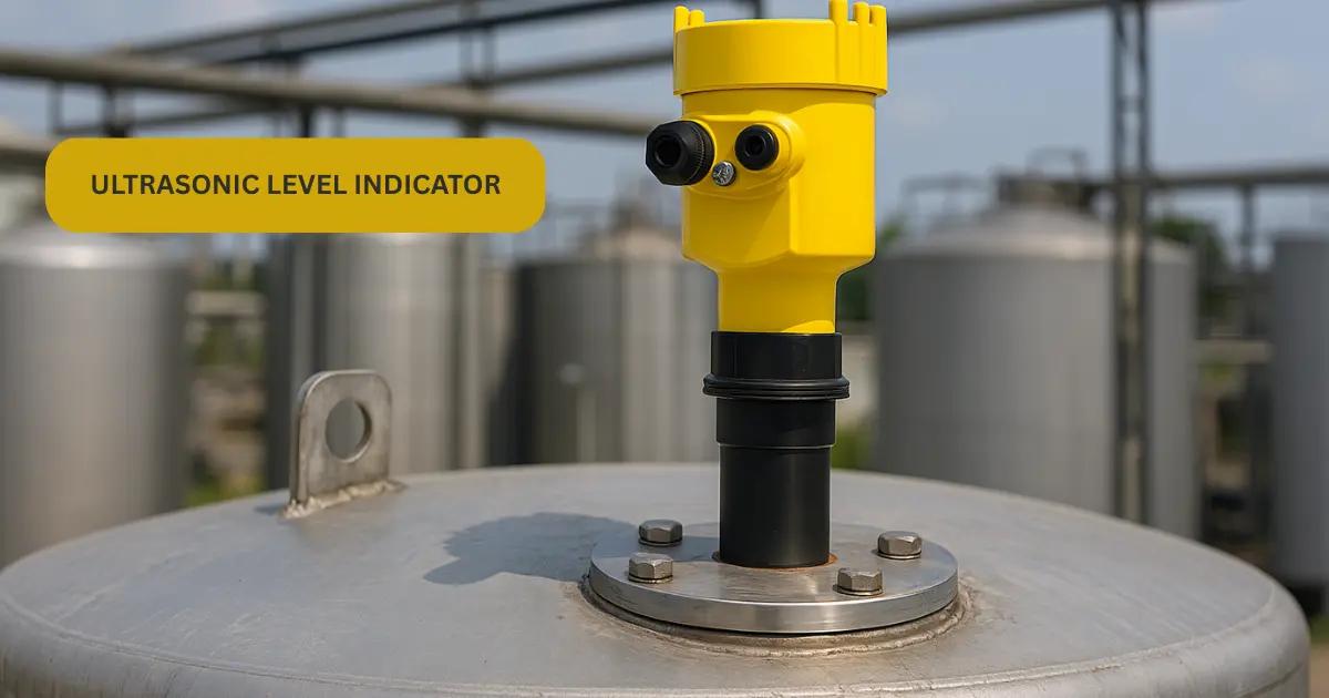
Ultrasonic level indicators are non-contact measurement devices that determine the level of liquids or solids in tanks, vessels, silos, and open channels by emitting ultrasonic sound waves and measuring the time it takes for the echo to return. Unlike traditional float switches or dipsticks that require direct contact with the material being measured, ultrasonic level indicators operate from a safe distance above the material surface, making them ideal for corrosive, viscous, or hazardous substances.
These sensors typically operate at frequencies between 20 kHz and 200 kHz—well above the range of human hearing. The ultrasonic level sensor consists of a transducer that both generates and receives ultrasonic pulses, processing electronics that calculate the distance based on time-of-flight measurements, and output circuitry that converts this information into standardized signals such as 4-20mA analog outputs or digital communication protocols.
The fundamental principle behind ultrasonic level measurement is elegantly simple: sound waves travel at a known speed through air (approximately 343 meters per second at 20°C), so by measuring the time between transmission and echo reception, the sensor can accurately calculate the distance to the material surface. This distance is then subtracted from the known tank height to determine the actual level.
Modern ultrasonic level transmitters incorporate advanced signal processing algorithms that filter out false echoes, compensate for temperature variations, and provide reliable measurements even in challenging conditions with foam, turbulence, or obstructions in the beam path.
How Ultrasonic Level Sensors Work: The Science Behind Non-Contact Measurement
The ultrasonic level sensor working principle is based on the time-of-flight measurement technique, which leverages the predictable behavior of sound waves traveling through a medium. Understanding this principle is essential for proper sensor selection and installation.
When an ultrasonic level transmitter is activated, its piezoelectric transducer converts electrical energy into mechanical vibrations, generating a short burst of ultrasonic sound waves. These waves propagate downward through the air (or other gas) in the tank headspace toward the material surface. Upon striking the liquid or solid surface, a portion of the acoustic energy reflects back toward the sensor as an echo.
The same transducer that generated the pulse now switches to receive mode, detecting the returning echo. The sensor’s microprocessor precisely measures the elapsed time between pulse transmission and echo reception—typically measured in microseconds. Using the formula Distance = (Speed of Sound × Time) / 2, the sensor calculates the distance to the material surface. The division by two accounts for the round-trip travel of the sound wave.
Temperature significantly affects the speed of sound in air, which is why quality ultrasonic level sensors incorporate temperature compensation. The speed of sound increases by approximately 0.6 m/s for every 1°C rise in temperature. Advanced sensors include built-in temperature sensors that automatically adjust calculations to maintain accuracy across varying ambient conditions.
Signal processing algorithms play a crucial role in distinguishing the true surface echo from false echoes caused by tank internals, agitators, fill pipes, or foam layers. Modern sensors use techniques such as echo profiling, where the sensor maps the entire echo pattern and identifies the strongest, most consistent return as the actual surface level. Some sophisticated units employ adaptive algorithms that learn the tank’s echo signature over time, improving accuracy and reliability.
Key Components of Ultrasonic Level Measurement Systems
A complete ultrasonic level measurement system comprises several critical components that work together to deliver accurate, reliable level data. Understanding these components helps in proper system design and troubleshooting.
The ultrasonic transducer serves as the heart of the system, functioning as both transmitter and receiver. Most industrial sensors use piezoelectric ceramic elements that vibrate at ultrasonic frequencies when voltage is applied. The transducer’s frequency, beam angle, and acoustic power determine its suitability for specific applications. Lower frequencies (20-40 kHz) provide longer range and better penetration through dust or vapor, while higher frequencies (100-200 kHz) offer better resolution for shorter-range applications.
The signal processing unit contains the microprocessor, timing circuits, and algorithms that control pulse generation, measure echo return times, and convert these measurements into level readings. This unit handles temperature compensation, false echo rejection, and output signal conditioning. In modern digital sensors, this component also manages communication protocols such as HART, Profibus, or Modbus.
The housing and mounting hardware protect the electronics from environmental conditions and provide secure installation. Industrial-grade sensors feature weatherproof enclosures rated to IP65, IP67, or even IP68 standards for submersible applications. The mounting flange or thread connection must be compatible with the tank’s nozzle size and pressure rating.
The output interface converts the measured level into usable signals for control systems and displays. The industry-standard ultrasonic level sensor 4-20mA output provides a current loop signal proportional to the measured level, with 4mA typically representing empty and 20mA representing full. Many sensors also offer relay outputs for high/low alarms and digital communication interfaces for integration with SCADA systems.
Optional components include display modules for local indication, programming interfaces for configuration, and remote mounting kits that separate the electronics from the transducer in high-temperature applications.
Advantages of Ultrasonic Level Indicators Over Traditional Methods
The widespread adoption of ultrasonic level indicators across industries stems from their numerous advantages over traditional contact-based measurement methods such as float switches, dipsticks, and pressure transmitters.
Non-contact measurement stands as the most significant advantage. Since the sensor never touches the measured material, there are no moving parts to wear out, corrode, or become fouled. This characteristic makes ultrasonic sensors ideal for corrosive chemicals, viscous liquids, abrasive slurries, and sticky materials that would quickly damage or coat contact-based sensors. The absence of mechanical wear translates to longer service life and reduced maintenance costs.
Versatility across materials represents another key benefit. A single ultrasonic level sensor for tanks can measure virtually any liquid or solid material, regardless of its dielectric constant, conductivity, or density. This universal applicability contrasts sharply with capacitance or conductivity probes that require specific material properties to function properly.
Easy installation and retrofitting make ultrasonic sensors attractive for both new construction and existing facility upgrades. Most sensors mount on standard tank nozzles without requiring tank modifications, welding, or process shutdown. The non-intrusive nature means no penetration of the tank wall below the liquid level, eliminating potential leak points and simplifying pressure vessel certifications.
Continuous level measurement provides real-time data rather than the discrete point detection offered by float switches or level switches. This continuous measurement enables better inventory management, more precise process control, and early detection of abnormal conditions. The analog output signal integrates seamlessly with modern control systems and SCADA platforms.
Safety in hazardous environments is enhanced because ultrasonic sensors can be specified with intrinsically safe or explosion-proof certifications for use in classified areas. The non-contact principle means no sparks or hot surfaces that could ignite flammable vapors, and the sensor can be mounted outside the hazardous zone while measuring through a non-metallic tank wall or standpipe.
Cost-effectiveness emerges when considering total cost of ownership. While the initial purchase price of an ultrasonic level transmitter may exceed simple mechanical switches, the elimination of maintenance, longer service life, and reduced downtime typically result in lower lifetime costs. Additionally, a single sensor can replace multiple point-level switches, reducing both hardware costs and installation complexity.
Limitations and Considerations When Using Ultrasonic Sensors
Despite their many advantages, ultrasonic level indicators have limitations that must be understood to ensure successful implementation. Recognizing these constraints helps engineers select the appropriate technology for each application.
Environmental conditions significantly impact ultrasonic sensor performance. Heavy foam layers can absorb or scatter ultrasonic waves, preventing reliable echo returns. Dense vapor clouds, mist, or dust can attenuate the signal, reducing effective range. Extreme temperature variations affect both the speed of sound and the sensor’s electronics, potentially requiring special high-temperature models or remote mounting configurations.
Pressure limitations restrict the use of standard ultrasonic sensors in high-pressure applications. Most industrial ultrasonic sensors are rated for relatively low pressures (typically up to 3-5 bar), as the transducer face must be exposed to the tank atmosphere. For high-pressure vessels, alternative technologies such as guided wave radar or pressure transmitters may be more suitable.
Tank geometry and obstructions can create measurement challenges. Ultrasonic waves spread in a cone-shaped beam, so narrow tanks or tanks with multiple internal structures may generate false echoes. Agitators, heating coils, and fill pipes within the beam path can reflect stronger signals than the actual liquid surface, confusing the sensor. Proper mounting location selection and the use of advanced echo processing algorithms can mitigate these issues.
Material surface characteristics affect echo strength. Highly turbulent surfaces scatter ultrasonic energy, weakening the return signal. Very low-dielectric materials like liquefied gases or hydrocarbons with dielectric constants below 1.5 may provide weak echoes. Angled surfaces or materials with sound-absorbing properties can deflect or absorb the ultrasonic beam, preventing detection.
Dead zones exist near the sensor face where measurement is impossible. This blocking distance, typically 6-12 inches depending on the sensor model, represents the minimum distance required for the transducer to switch from transmit to receive mode and for the echo to be distinguishable from the transmitted pulse. Tank designs must account for this dead zone to ensure full-range measurement capability.
Accuracy considerations reveal that while ultrasonic sensors provide good accuracy (typically ±0.25% to ±0.5% of range), they may not match the precision of some competing technologies like radar or servo-driven mechanical systems in demanding applications. For custody transfer or applications requiring accuracy better than ±3mm, alternative technologies should be considered.
Industrial Applications: Where Ultrasonic Level Indicators Excel
The versatility and reliability of ultrasonic level indicators have made them the preferred choice across numerous industries and applications. Understanding where these sensors excel helps identify opportunities for implementation.
Water and wastewater treatment facilities extensively use ultrasonic water level sensors for monitoring storage tanks, clarifiers, wet wells, and open channels. The non-contact principle prevents contamination and eliminates maintenance issues associated with submersible sensors in dirty water. Municipal water systems rely on ultrasonic sensors for reservoir level monitoring, pump station control, and distribution network management. The sensors’ ability to measure through foam and turbulence makes them ideal for aeration tanks and chemical dosing systems.
Chemical processing plants benefit from ultrasonic measurement of corrosive and hazardous liquids without sensor degradation. Acids, bases, solvents, and reactive chemicals can be monitored safely from above the liquid surface. The intrinsically safe versions of ultrasonic level transmitters meet stringent safety requirements for flammable liquid storage and processing. Batch reactor level control, day tank monitoring, and chemical inventory management all leverage ultrasonic technology.
Food and beverage production facilities use ultrasonic sensors for hygienic level measurement in processing tanks, storage silos, and mixing vessels. The non-contact principle means no product contamination and easy cleaning validation. Dairy processing, brewing, soft drink production, and edible oil storage all employ ultrasonic sensors. Models with sanitary certifications and food-grade materials meet FDA and EHEDG requirements.
Petroleum and petrochemical industries deploy ultrasonic sensors for crude oil storage, refined product tanks, and intermediate storage in refineries. The ability to measure through hydrocarbon vapors and the availability of explosion-proof housings make ultrasonic sensors suitable for these hazardous environments. Tank farms use networked ultrasonic sensors for inventory management and leak detection.
Bulk solids handling operations in cement plants, grain elevators, mining operations, and powder processing facilities use ultrasonic sensors for silo level monitoring. The sensors can detect the surface of granular materials, powders, and aggregates without the bridging and coating issues that plague mechanical systems. Dust-penetrating low-frequency sensors provide reliable measurement even in dusty conditions.
Pharmaceutical manufacturing utilizes ultrasonic sensors for precise level control in API (Active Pharmaceutical Ingredient) production, solvent recovery systems, and clean-in-place (CIP) operations. The non-contact measurement prevents cross-contamination between batches, and the sensors’ accuracy supports compliance with stringent quality control requirements.
Environmental monitoring applications include groundwater level measurement, stormwater management, and flood warning systems. Ultrasonic level sensor Arduino projects have made this technology accessible for educational and small-scale environmental monitoring, demonstrating the technology’s scalability from industrial to hobbyist applications.
Ultrasonic Level Indicators for Liquids vs. Solids: Key Differences
While ultrasonic level indicators can measure both liquids and solids, the characteristics of each application require different considerations for optimal performance.
Liquid level measurement generally provides more consistent results because liquid surfaces are relatively uniform and reflective. The smooth surface of most liquids creates a strong, specular reflection that returns directly to the sensor. However, liquids present challenges such as foam formation, surface turbulence from filling or agitation, and vapor clouds that can interfere with the ultrasonic beam. The ultrasonic liquid level sensor must be selected with appropriate frequency and beam angle to handle these conditions. Lower viscosity liquids may exhibit more surface movement, requiring sensors with advanced signal processing to filter out noise from waves and ripples.
Solid level measurement introduces different complexities. Bulk solids typically have irregular, uneven surfaces that scatter ultrasonic energy in multiple directions rather than reflecting it directly back to the sensor. This diffuse reflection reduces echo strength, requiring sensors with higher acoustic power and more sensitive receivers. The angle of repose—the natural slope formed when granular material is poured—means the surface may not be perpendicular to the sensor beam, further weakening the return signal.
Dust generation during filling operations can temporarily blind ultrasonic sensors measuring solids. Sensors designed for bulk solids applications incorporate algorithms that hold the last valid reading during dust events and resume measurement once the dust settles. Some models use lower frequencies (20-30 kHz) that penetrate dust clouds more effectively than higher frequencies.
Material bridging and rat-holing in silos can create false level indications with solids. Bridging occurs when material forms an arch above the actual material level, while rat-holing creates a vertical cavity in the material. Ultrasonic sensors may detect these formations rather than the true bulk level. Multiple sensors at different locations or supplementary point-level switches can help detect these conditions.
Temperature effects differ between applications. Liquid storage often maintains relatively stable temperatures, while bulk solid storage in silos may experience significant temperature stratification, with warmer air near the top and cooler air near the material surface. This temperature gradient bends the ultrasonic beam, potentially causing measurement errors. Advanced sensors compensate for these effects through multiple temperature sensors or beam-steering algorithms.
Sensor mounting requirements also vary. For liquids, the sensor should be mounted away from fill streams, agitators, and tank walls to avoid false echoes. For solids, mounting at the center of the silo top provides the best view of the material cone, though offset mounting may be necessary to avoid fill chutes or dust collectors.
Choosing the Right Ultrasonic Level Indicator: Selection Criteria
Selecting the appropriate ultrasonic level sensor requires careful evaluation of application requirements, environmental conditions, and performance specifications. A systematic approach ensures optimal sensor performance and long-term reliability.
Measurement range represents the primary specification. Ultrasonic sensors are available with ranges from less than 1 meter to over 70 meters. The required range depends on tank height minus the dead zone at the top. It’s advisable to select a sensor with a range slightly exceeding the actual measurement distance to maintain accuracy at the extremes. Longer-range sensors typically use lower frequencies, while short-range applications benefit from higher frequencies that provide better resolution.
Accuracy requirements must align with the application’s needs. Standard industrial ultrasonic level transmitters offer accuracy of ±0.25% to ±0.5% of the measured range. High-precision models can achieve ±0.15% or better. For inventory management and custody transfer, tighter accuracy specifications may justify higher costs, while simple overfill prevention may accept looser tolerances.
Process conditions including temperature, pressure, and material characteristics heavily influence sensor selection. Operating temperature ranges vary widely among models, from -40°C to +80°C for standard versions, with special high-temperature models available for applications up to +200°C using remote mounting. Pressure ratings typically range from atmospheric to 3-5 bar for standard sensors. Material compatibility considerations include whether the process generates foam, vapor, or dust that could interfere with measurement.
Output signal requirements should match the control system’s inputs. The standard ultrasonic level sensor 4-20mA output works with most PLCs and controllers, but digital protocols like HART, Profibus, Modbus, or Foundation Fieldbus enable advanced diagnostics and remote configuration. Relay outputs for alarms and local displays for operator interface may be required.
Environmental protection ratings ensure the sensor withstands installation conditions. Indoor applications may only require IP65 protection, while outdoor installations exposed to weather need IP67 or IP68 ratings. Corrosive atmospheres may necessitate special housing materials like 316 stainless steel or plastic composites.
Hazardous area certifications are mandatory for installations in classified locations. Intrinsically safe (IS) versions are available for Zone 0/Division 1 areas, while explosion-proof housings suit less stringent classifications. Certifications from ATEX, IECEx, FM, or CSA should match the facility’s requirements.
Mounting configuration options include threaded connections (typically 1.5″ to 2″ NPT or G threads), flanged connections (DN50 to DN200), and hygienic tri-clamp fittings for food and pharmaceutical applications. The mounting orientation should be vertical for best results, though some sensors tolerate slight angles.
Budget considerations extend beyond the ultrasonic level transmitter price to include installation costs, commissioning, and lifecycle expenses. While premium sensors cost more initially, their advanced features, better accuracy, and longer service life often provide better value. Entry-level sensors may suffice for non-critical applications where occasional maintenance is acceptable.
Installation Best Practices for Accurate Measurements
Proper installation of ultrasonic level indicators is crucial for achieving accurate, reliable measurements and avoiding common problems that compromise performance. Following established best practices ensures optimal sensor operation.
Mounting location selection significantly impacts measurement quality. The sensor should be mounted vertically, pointing straight down at the material surface. Angled mounting reduces echo strength and introduces measurement errors. Position the sensor away from tank walls—a minimum distance of 1 meter from walls is recommended for large tanks, with proportionally smaller clearances for smaller vessels. This positioning prevents false echoes from wall reflections.
Avoiding obstructions in the beam path is essential. The ultrasonic beam spreads in a cone shape, with the beam angle typically ranging from 6° to 15° depending on frequency and sensor design. Map out the beam cone and ensure it doesn’t intersect with fill pipes, agitators, heating coils, or other internal structures. If obstructions are unavoidable, mount the sensor in a stilling well or standpipe that isolates it from turbulence and provides a clear measurement path.
Fill stream considerations require mounting the sensor away from incoming material streams. Filling operations create turbulence, splashing, and temporary mounding that can cause erratic readings. Position the sensor at least 500mm from fill points, or use baffles to deflect material away from the measurement zone. For tanks with center-fill configurations, offset mounting near the tank wall may provide more stable readings.
Electrical installation must follow proper wiring practices. Use shielded cable for the ultrasonic level sensor 4-20mA output to minimize electrical noise, especially in electrically noisy industrial environments. Maintain separation from high-voltage power cables and variable frequency drives. Ground the sensor housing properly to prevent ground loops and static buildup. Follow the manufacturer’s specifications for maximum cable length—typically 500 meters for 4-20mA signals, less for low-voltage digital communications.
Calibration and commissioning procedures ensure accurate measurements. Most modern sensors feature automatic calibration routines, but manual verification is recommended. The ultrasonic level transmitter calibration procedure typically involves measuring the empty tank distance, setting the span for the full tank level, and configuring the output scaling. Verify calibration by filling the tank to known levels and comparing sensor readings to reference measurements. Document the calibration settings and baseline echo profiles for future troubleshooting.
Environmental protection extends sensor life in harsh conditions. Even with appropriate IP ratings, additional measures like sunshades for outdoor installations, heating elements for freezing conditions, and protective coatings for corrosive atmospheres can improve reliability. Ensure the transducer face remains clean and unobstructed—some installations benefit from air purge systems that keep the sensor face clear of condensation, dust, or material buildup.
Configuration optimization involves adjusting sensor parameters to match application conditions. Set appropriate damping values to filter out noise from turbulent surfaces while maintaining acceptable response time. Configure false echo suppression to ignore known reflections from tank internals. Adjust temperature compensation settings if the sensor’s internal temperature sensor doesn’t accurately represent the tank atmosphere temperature. Enable blocking distance settings to ignore the dead zone and any near-field obstructions.
Common Troubleshooting Issues and Solutions
Even properly installed ultrasonic level indicators may occasionally experience problems. Understanding common issues and their solutions enables quick diagnosis and resolution, minimizing downtime.
Erratic or fluctuating readings often result from surface turbulence, foam, or vapor interference. Solutions include increasing the damping or averaging time in the sensor configuration to smooth out rapid variations, adjusting the mounting position away from fill streams or agitators, or selecting a lower frequency sensor that better penetrates foam and vapor. For persistent foam issues, consider switching to guided wave radar technology, which is less affected by foam layers.
Loss of signal or no echo detected indicates the sensor isn’t receiving a usable return signal. Check for obstructions in the beam path, excessive dust or vapor density, or material buildup on the transducer face. Verify that the material surface is within the sensor’s measurement range and above the blocking distance. Inspect the transducer face for damage or contamination and clean if necessary. If the tank is empty, ensure the sensor is configured to handle the maximum range condition.
Incorrect level readings that are consistently offset from the true level suggest calibration errors or environmental factors. Verify the empty and full calibration points match the actual tank dimensions. Check that temperature compensation is functioning correctly—significant temperature changes without proper compensation can introduce errors of several centimeters. Review the tank geometry to ensure the sensor’s mounting position provides a clear view of the material surface at all levels.
False high-level alarms may occur due to false echoes from tank internals being interpreted as the material surface. Use the sensor’s echo curve or profile display to identify false echoes and configure the sensor to ignore them. Adjust the sensitivity or threshold settings to require stronger echoes for valid measurements. In some cases, relocating the sensor to a different mounting position eliminates problematic reflections.
Slow response time can result from excessive damping or averaging settings. While some filtering is necessary to smooth turbulent surfaces, too much damping makes the sensor sluggish in responding to actual level changes. Reduce damping values incrementally while monitoring for increased noise in the output signal. Balance responsiveness against stability based on the application’s control requirements.
Communication failures with digital protocols require systematic diagnosis. Verify proper wiring, correct protocol settings, and unique device addresses. Check for adequate power supply voltage—low voltage can cause communication errors even if the sensor continues to measure. Inspect for electrical noise sources that may corrupt digital signals and improve shielding or routing if necessary. Consult the sensor’s diagnostic registers for specific error codes that indicate the nature of the communication problem.
Condensation on the transducer face in applications with temperature differentials can block or attenuate the ultrasonic beam. Solutions include installing a sunshade to reduce solar heating, using a heated sensor model, or implementing an air purge system that directs a small flow of dry air across the transducer face. Ensure the sensor housing is properly sealed to prevent moisture ingress into the electronics.
Ultrasonic vs. Radar vs. Capacitance: Technology Comparison
Selecting the optimal level measurement technology requires understanding the strengths and limitations of competing approaches. Comparing ultrasonic level indicators with radar and capacitance technologies helps identify the best solution for specific applications.
Ultrasonic vs. radar level sensors represents a common decision point. The radar level sensor working principle uses electromagnetic waves rather than sound waves, operating at microwave frequencies (typically 6 GHz, 26 GHz, or 80 GHz). Radar sensors excel in challenging conditions where ultrasonic sensors struggle: they’re unaffected by temperature, pressure, or vapor density, and they can measure through heavy foam and dust. Radar provides superior accuracy (often ±1-2mm) and works in vacuum conditions where ultrasonic sensors cannot function.
However, ultrasonic level sensors offer significant advantages in many applications. They cost substantially less than radar systems—often 30-50% less for comparable range and features. Ultrasonic sensors are simpler to install and commission, with less sensitivity to antenna contamination or coating. For non-critical applications with moderate accuracy requirements, ultrasonic technology provides excellent value. The technology also works better with low-dielectric materials like hydrocarbons, where radar signals may not reflect adequately.
Pressure and process conditions often determine the choice. Ultrasonic sensors suit atmospheric or low-pressure applications (typically up to 5 bar), while radar handles high-pressure vessels up to 100 bar or more. Extreme temperatures favor radar, which can operate from -200°C to +400°C with appropriate antenna designs, whereas ultrasonic sensors typically max out at +200°C with remote mounting.
Capacitance level sensors represent a different approach, measuring the change in capacitance between a probe and the tank wall (or a reference electrode) as material level changes. Capacitance probes require contact with the material, making them unsuitable for corrosive or coating materials that would foul the probe. They also require the material to have adequate dielectric properties—typically a dielectric constant above 1.4 for reliable operation.
The key advantage of ultrasonic level indicators over capacitance probes is the non-contact principle, which eliminates coating, corrosion, and mechanical wear issues. Ultrasonic sensors work with any material regardless of dielectric properties, while capacitance probes fail with very low-dielectric materials like liquefied gases. However, capacitance probes can measure in high-pressure vessels and provide interface level detection between two liquids, capabilities beyond standard ultrasonic sensors.
Installation and maintenance considerations favor ultrasonic technology in many cases. Ultrasonic sensors mount externally on tank nozzles without penetrating below the liquid level, simplifying installation and eliminating potential leak points. Capacitance probes require insertion into the tank, often necessitating process shutdown for installation or maintenance. Radar sensors also mount externally but require careful antenna selection and positioning to avoid contamination.
Application suitability ultimately drives technology selection. Choose ultrasonic sensors for general-purpose liquid and bulk solid level measurement in atmospheric or low-pressure tanks where moderate accuracy suffices and cost-effectiveness is important. Select radar for high-accuracy applications, extreme conditions (temperature, pressure, vacuum), heavy foam or vapor, or when measuring very low-dielectric materials. Opt for capacitance probes when measuring interface levels, in high-pressure vessels with conductive materials, or when point-level detection rather than continuous measurement is adequate.
Future Trends in Ultrasonic Level Measurement Technology
The evolution of ultrasonic level indicators continues as manufacturers integrate new technologies and respond to changing industrial requirements. Understanding emerging trends helps engineers prepare for next-generation capabilities and plan future installations.
Artificial intelligence and machine learning are being incorporated into advanced ultrasonic sensors to improve measurement reliability and reduce false readings. AI algorithms analyze echo patterns over time, learning to distinguish true surface echoes from false reflections caused by tank internals or process conditions. These smart sensors adapt to changing conditions automatically, reducing the need for manual configuration and maintenance. Predictive maintenance capabilities alert operators to developing problems before they cause measurement failures.
Wireless communication and IIoT integration are transforming how ultrasonic level transmitters connect to control systems. Battery-powered wireless sensors eliminate installation costs for signal cables, making level monitoring economically viable in remote or difficult-to-access locations. Integration with Industrial Internet of Things (IIoT) platforms enables cloud-based monitoring, analytics, and remote configuration. LoRaWAN, NB-IoT, and other low-power wide-area network technologies extend wireless range to kilometers, supporting distributed tank farms and environmental monitoring applications.
Multi-sensor fusion combines ultrasonic measurement with complementary technologies in single devices. Hybrid sensors incorporating both ultrasonic and radar measurement automatically select the optimal technology based on current conditions, providing reliability across a wider range of applications. Integration of temperature, pressure, and humidity sensors enables more sophisticated compensation algorithms and provides additional process data from a single installation point.
Enhanced signal processing leverages faster processors and advanced algorithms to extract usable signals from increasingly challenging conditions. Adaptive filtering techniques separate weak echoes from noise, extending measurement capability in applications with heavy foam, dust, or vapor. Frequency-agile sensors that can adjust their operating frequency optimize performance for varying conditions, using lower frequencies for long range or dust penetration and higher frequencies for improved resolution when conditions permit.
Miniaturization and cost reduction through advances in MEMS (Micro-Electro-Mechanical Systems) technology are making ultrasonic sensors smaller and more affordable. Compact sensors enable level measurement in small containers and tight spaces previously inaccessible to traditional sensors. Lower costs expand the economic viability of ultrasonic measurement to applications that previously relied on simple mechanical switches or manual dipstick readings. The proliferation of ultrasonic level sensor Arduino projects demonstrates how accessible this technology has become for educational and small-scale applications.
Improved environmental resistance through advanced materials and coatings extends sensor life in harsh conditions. Chemically resistant transducer faces withstand aggressive vapors and cleaning chemicals in pharmaceutical and food processing applications. Self-cleaning coatings prevent material buildup that could interfere with measurements. Enhanced sealing technologies improve reliability in outdoor installations exposed to extreme weather, dust, and moisture.
Cybersecurity features are being built into networked sensors as industrial facilities become more connected and vulnerable to cyber threats. Encrypted communication protocols, secure authentication, and firmware verification protect against unauthorized access and tampering. These security measures become increasingly important as sensors connect to enterprise networks and cloud platforms.
Energy harvesting technologies promise self-powered sensors that never require battery replacement. Piezoelectric, thermoelectric, and photovoltaic energy harvesting systems capture ambient energy to power low-power ultrasonic sensors, enabling truly maintenance-free installations in remote locations. While still emerging, these technologies could revolutionize environmental monitoring and distributed tank farm applications.
The future of ultrasonic level measurement lies in smarter, more connected, and more reliable sensors that seamlessly integrate with digital industrial ecosystems. As these technologies mature, ultrasonic sensors will continue to expand their application range while becoming easier to install, configure, and maintain. Engineers and facility managers who stay informed about these developments will be better positioned to leverage next-generation capabilities for improved process control, safety, and efficiency.
Frequently Asked Questions
How do ultrasonic level indicators work?
Ultrasonic level indicators work by emitting high-frequency sound waves (typically 20-200 kHz) toward the material surface and measuring the time it takes for the echo to return. The sensor calculates the distance using the formula: Distance = (Time × Speed of Sound) / 2. This non-contact measurement method provides accurate level readings for both liquids and solids without physically touching the material, making it ideal for corrosive, viscous, or hazardous substances.
How accurate are ultrasonic level sensors?
Ultrasonic level indicators typically offer accuracy within ±0.25% to ±0.5% of the measured range under optimal conditions. Most industrial-grade sensors provide accuracy of ±3mm to ±10mm depending on the application and environmental factors. Accuracy can be affected by temperature variations, vapor, foam, and turbulence, but modern sensors include temperature compensation and advanced signal processing to maintain reliable measurements across diverse conditions.
What are the main advantages of ultrasonic level sensors?
The primary advantages include non-contact measurement (no wear or contamination), suitability for corrosive and hazardous materials, easy installation without tank penetration, and minimal maintenance requirements. Ultrasonic level indicators also work effectively with both liquids and solids, offer continuous level monitoring, and are cost-effective compared to radar systems. They’re particularly valuable in applications where contact sensors would degrade quickly or contaminate the measured material.
What are the disadvantages of ultrasonic level sensors?
The main limitations include sensitivity to temperature fluctuations, vapor, and foam which can absorb or scatter sound waves. Ultrasonic sensors may struggle with extreme turbulence, very low dielectric materials, and vacuum conditions where sound cannot travel. They also have a “dead zone” near the sensor face (typically 6-18 inches) where measurements cannot be taken, and performance can be affected by dust, mist, or pressure changes in the environment.
Can ultrasonic sensors detect water levels accurately?
Yes, ultrasonic level indicators are excellent for water level detection and are widely used in water treatment plants, reservoirs, wells, and wastewater applications. Water provides a good reflective surface for ultrasonic waves, enabling accurate measurements. These sensors work effectively in open channels, tanks, and sumps, making them a popular choice for municipal water management, irrigation systems, and flood monitoring applications.
What situations should be avoided when installing ultrasonic level sensors?
Avoid installing ultrasonic sensors where they point directly at filling streams (which create turbulence and false echoes), near tank walls or obstructions that cause interference, or in locations with excessive foam or vapor that absorbs sound waves. Additionally, avoid mounting in areas with extreme temperature gradients, high dust concentrations, or where the sensor beam might reflect off internal structures rather than the material surface.
What does 0.034 represent in ultrasonic sensor calculations?
The value 0.034 represents the speed of sound in centimeters per microsecond (or 340 meters per second) at room temperature. This constant is used in the distance calculation formula for ultrasonic sensors: Distance (cm) = (Duration × 0.034) / 2. The division by 2 accounts for the round-trip travel time of the sound wave from the sensor to the target and back.
How do ultrasonic level indicators compare to radar level sensors?
Ultrasonic level indicators are more cost-effective and work well for most standard applications, while radar sensors excel in challenging conditions with foam, vapor, extreme temperatures, or vacuum environments. Radar is unaffected by temperature and pressure changes but costs significantly more. Ultrasonic sensors are typically preferred for water, wastewater, and general chemical applications, while radar is chosen for high-temperature processes, pressurized vessels, and applications with heavy vapor or foam.
What output signals do ultrasonic level sensors provide?
Most ultrasonic level indicators provide standard industrial outputs including 4-20mA analog signals (most common), digital protocols like HART, Modbus, or Profibus, and relay outputs for alarm functions. The 4-20mA output is particularly popular because it’s compatible with most control systems, provides continuous level data, and allows for long cable runs without signal degradation. Many modern sensors also offer display screens and wireless communication options.
You May Also Like

7 Reasons Why WPS Desktop Is a Must-Have Tool in 2026

Reducing Cyber Risk: Practical Guide for UK Businesses 2024

Biogas Odour Control: Carbon Filtration Systems Guide