Steam Turbine Refurbishment: Complete Inspection Guide
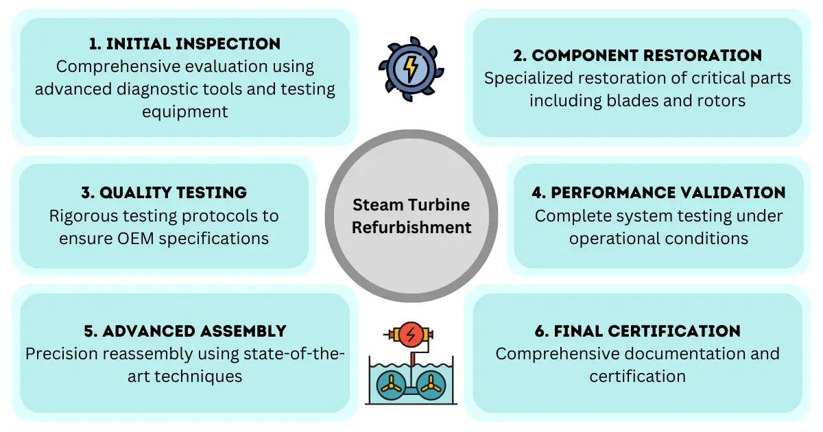
When a steam turbine refurbishment becomes necessary, maintenance engineers and plant managers face critical decisions that can impact operational efficiency, safety, and long-term costs. Steam turbine refurbishment is a comprehensive process that involves systematic inspection, fault analysis, component reconditioning, and performance restoration of aging or damaged turbines to extend their operational life and restore optimal efficiency. This detailed technical guide walks through the complete steam turbine refurbishment process—from initial diagnostic assessments through final commissioning—providing the authoritative information needed to make informed maintenance decisions and execute successful turbine restoration projects.
What Is Steam Turbine Refurbishment and When Is It Needed?
Steam turbine refurbishment is a systematic restoration process that returns an aging or degraded turbine to near-original performance specifications through inspection, repair, reconditioning, and replacement of worn components. Unlike routine maintenance or minor repairs, refurbishment represents a comprehensive overhaul that addresses multiple systems simultaneously, typically requiring complete disassembly and detailed component-level evaluation.
The decision to pursue steam turbine refurbishment rather than replacement typically arises under several specific circumstances. Turbines experiencing declining efficiency—often manifested as reduced power output, increased steam consumption, or elevated exhaust temperatures—are prime candidates for refurbishment. Vibration issues that cannot be resolved through balancing or alignment adjustments often indicate internal component degradation requiring comprehensive intervention. Additionally, turbines approaching or exceeding their design life expectancy benefit from proactive refurbishment to prevent catastrophic failures.
Major service providers specializing in turbine repair services, including established companies offering comprehensive steam turbine services, typically recommend refurbishment intervals based on operating hours, start-stop cycles, and performance trending data. For most industrial steam turbines, major refurbishment becomes economically justified after 40,000 to 100,000 operating hours, though specific intervals vary based on operating conditions, steam quality, and load cycling frequency.
The economic threshold for refurbishment versus replacement generally favors refurbishment when the total restoration cost remains below 50-60% of new equipment replacement costs. This calculation must account for extended downtime, lost production revenue, and the potential for discovering additional problems during disassembly. Turbines with unique configurations, custom designs, or those integrated into specialized processes often justify refurbishment even at higher cost ratios due to replacement complexity.
Initial Inspection: Visual Assessment and Diagnostic Testing
The turbine inspection process begins with comprehensive visual assessments and non-destructive testing while the unit remains operational or during scheduled shutdowns. This preliminary evaluation establishes baseline condition data and identifies critical areas requiring detailed examination during full disassembly. Experienced technicians from turbine repair services companies conduct systematic external inspections, documenting casing condition, foundation integrity, piping connections, and auxiliary system status.
Vibration analysis represents the cornerstone of diagnostic testing for operating turbines. Technicians install accelerometers at standardized bearing housing locations, collecting data across multiple operating loads and speeds. Spectral analysis of vibration signatures reveals bearing wear patterns, rotor imbalance, misalignment conditions, and blade damage through characteristic frequency patterns. Trending this data over time provides early warning of developing problems and helps prioritize refurbishment scope.
Thermal imaging surveys identify hot spots indicating steam leaks, insulation degradation, or internal flow path obstructions. Infrared cameras capture temperature distributions across casing surfaces, valve bodies, and piping connections during operation. Temperature anomalies often correlate with internal seal failures, blade tip clearance issues, or steam path deviations that require correction during refurbishment.
Performance testing under controlled conditions establishes efficiency baselines for comparison after refurbishment completion. Engineers measure steam flow rates, inlet and exhaust pressures, temperatures at multiple stages, and power output across the operating range. This data quantifies efficiency degradation and helps establish realistic performance improvement targets. Modern steam turbine maintenance protocols incorporate continuous performance monitoring systems that track efficiency trends and trigger refurbishment planning when degradation exceeds predetermined thresholds.
Borescope inspections provide internal visual access without complete disassembly, particularly valuable for preliminary fault identification. Technicians insert fiber-optic cameras through inspection ports, examining blade conditions, seal clearances, and internal deposits. High-resolution imaging documents erosion patterns, corrosion damage, scaling buildup, and mechanical damage, informing refurbishment scope and component replacement requirements.
Fault Analysis: Common Steam Turbine Problems and Root Causes
Comprehensive steam turbine fault analysis identifies failure modes, determines root causes, and establishes corrective actions that prevent recurrence after refurbishment. The most prevalent failure mechanisms fall into distinct categories, each requiring specific diagnostic approaches and remediation strategies.
Blade failures represent the most critical fault category, manifesting as erosion, fatigue cracking, corrosion, or mechanical damage from foreign object impacts. Erosion typically affects last-stage blades in condensing turbines, where moisture droplets accelerate to supersonic velocities and impact blade surfaces. Solid particle erosion occurs in high-pressure stages when scale or contaminants enter the steam path. Fatigue failures develop from high-cycle loading, particularly in blades experiencing resonant vibration at specific operating speeds. Corrosion pitting and stress corrosion cracking affect blades exposed to contaminated steam containing chlorides, sulfates, or dissolved oxygen.
Rotor-related faults include thermal bowing, permanent deformation, journal wear, and coupling problems. Thermal bowing results from uneven heating during startup or shutdown, creating temporary or permanent rotor curvature that generates vibration. Shaft journals wear from bearing contact, particularly when lubrication systems fail or contamination enters bearing surfaces. Coupling misalignment or wear creates torsional vibration and fatigue loading on rotor components.
Bearing failures encompass journal bearing wear, thrust bearing damage, and lubrication system degradation. Babbitt bearing surfaces wear through normal operation, contamination, or inadequate oil film thickness. Thrust bearing failures occur when axial loads exceed design limits due to steam imbalance or control system malfunctions. Oil degradation, contamination with water or particulates, and inadequate cooling accelerate bearing deterioration.
Seal system failures allow steam leakage, reducing efficiency and potentially causing secondary damage. Labyrinth seal clearances increase through wear, thermal distortion, or rotor movement. Carbon ring seals crack, break, or wear excessively when subjected to thermal cycling or vibration. Gland seal steam systems fail when pressure control malfunctions or drain systems become blocked.
Casing and diaphragm problems include cracking, warping, erosion, and joint leakage. Thermal cycling induces fatigue cracks in high-stress areas, particularly around nozzle blocks and bolt holes. Differential expansion between casing halves creates alignment problems and seal clearance variations. Steam leakage past horizontal joint faces reduces efficiency and may cause erosion damage to adjacent components.
Control and protection system faults, while not mechanical failures, often necessitate upgrades during refurbishment. Governor valve sticking, actuator wear, and sensor drift degrade control response and efficiency. Overspeed trip systems require periodic testing and often benefit from modernization to current safety standards during major refurbishments.
Disassembly and Component Evaluation Process
Systematic disassembly following documented procedures ensures component preservation, enables thorough inspection, and facilitates accurate reassembly. Professional turbine repair services near me and specialized contractors follow standardized protocols that begin with comprehensive photographic documentation of as-found conditions, connection configurations, and component orientations before any disassembly work commences.
The disassembly sequence typically begins with auxiliary system disconnection, including steam piping, extraction lines, drains, instrumentation, and lubrication connections. Technicians carefully label and cap all connections, preserving alignment references and preventing contamination entry. Coupling removal follows, requiring precise measurement of coupling gaps, bolt torques, and alignment positions for reassembly reference.
Upper casing removal exposes internal components for inspection while the rotor remains in place on lower bearing pedestals. Technicians measure and record rotor position, bearing clearances, and seal gaps before disturbing any components. This data establishes baseline conditions and identifies areas requiring correction during reconditioning. Lifting the upper casing requires specialized rigging equipment and precise control to prevent damage to machined joint surfaces and internal components.
Diaphragm and nozzle block removal proceeds systematically from high-pressure to low-pressure stages, with each component tagged for position identification and inspection tracking. Technicians examine each diaphragm for cracks, erosion, distortion, and seal wear, documenting conditions with detailed photographs and dimensional measurements. Nozzle blocks receive particular attention, as erosion or deposits significantly impact stage efficiency.
Rotor extraction represents the most critical disassembly operation, requiring specialized lifting equipment, precise alignment control, and careful handling to prevent journal damage. Before lifting, technicians install protective sleeves over journals and coupling faces. The rotor is lifted vertically or horizontally depending on turbine configuration and facility capabilities, then transferred to inspection stands equipped with rotation capabilities and measurement systems.
Component evaluation during disassembly employs multiple inspection techniques. Visual examination identifies obvious damage, wear patterns, and corrosion. Dimensional measurements using micrometers, bore gauges, and coordinate measuring machines quantify wear and deformation. Non-destructive testing including magnetic particle inspection, liquid penetrant testing, and ultrasonic examination detects cracks and subsurface defects. Metallurgical analysis of failed components determines root causes and material suitability.
Documentation throughout disassembly creates a comprehensive condition assessment that guides reconditioning scope decisions. Inspection reports detail every component’s condition, provide repair recommendations, and estimate costs for various restoration options. This information enables informed decisions about repair versus replacement for individual components and overall refurbishment strategy.
Rotor Inspection and Balancing Procedures
Rotor inspection and reconditioning represent critical elements of steam turbine refurbishment, as rotor integrity directly impacts reliability, vibration levels, and operational safety. The rotor assembly undergoes comprehensive examination using multiple inspection techniques that detect surface and subsurface defects potentially compromising structural integrity.
Visual inspection identifies obvious damage including blade attachment wear, journal scoring, coupling face damage, and corrosion. Technicians examine blade roots for fretting wear, cracking, and looseness. Shroud contact areas reveal rub patterns indicating clearance problems or rotor deflection during operation. Coupling faces show wear patterns that indicate misalignment or inadequate lubrication.
Dimensional inspection quantifies rotor geometry using precision measurement equipment. Technicians measure journal diameters at multiple locations, documenting wear patterns and out-of-round conditions. Runout measurements with dial indicators reveal rotor straightness and identify areas requiring correction. Blade tip diameters establish clearance requirements for reassembly. Coupling face runout measurements ensure proper alignment capability after refurbishment.
Non-destructive testing detects cracks and material defects not visible during visual inspection. Magnetic particle inspection examines ferromagnetic rotor components, revealing surface and near-surface cracks in blade attachments, keyways, and highly stressed areas. Liquid penetrant testing inspects non-magnetic materials and provides high sensitivity for surface crack detection. Ultrasonic testing examines rotor forgings for internal defects, particularly in bore areas and highly stressed sections. Eddy current testing inspects blade attachment areas and detects fatigue cracks in early stages.
Rotor reconditioning addresses identified defects through various techniques. Journal surfaces receive precision grinding to restore geometry and remove damage, maintaining adequate shaft diameter for bearing clearances. Damaged coupling faces undergo machining to restore flatness and perpendicularity. Blade attachment areas may require weld repair and remachining when wear or cracking is detected, though replacement often proves more economical for severely damaged rotors.
Dynamic balancing restores rotor balance to specifications that ensure smooth operation across the operating speed range. Technicians mount the rotor in precision balancing machines capable of measuring unbalance at multiple planes simultaneously. Initial spin tests identify unbalance magnitude and angular location. Correction involves adding or removing material at specific locations—typically through drilling balance holes or attaching balance weights. Multi-plane balancing addresses both static and dynamic unbalance, essential for long rotors with multiple blade rows.
High-speed balancing in specialized facilities simulates actual operating conditions, particularly important for high-speed turbines where centrifugal forces affect balance distribution. Some refurbishment projects include field balancing after installation to account for foundation effects, coupling influences, and actual operating conditions. Modern balancing standards typically target residual unbalance levels below 4W/N grams per plane, where W represents rotor weight in kilograms and N represents maximum operating speed in RPM.
Blade Reconditioning and Replacement Criteria
Turbine blade refurbishment requires careful evaluation of each blade’s condition against established acceptance criteria, with decisions balancing repair costs against replacement expenses and performance implications. Blade assessment considers multiple damage mechanisms and their impact on structural integrity, aerodynamic performance, and remaining service life.
Erosion damage assessment quantifies material loss and evaluates its impact on blade strength and efficiency. Leading edge erosion in high-pressure stages results from solid particle impacts, while trailing edge erosion in low-pressure stages occurs from moisture droplet impingement. Measurement techniques include profile comparison against original drawings, ultrasonic thickness gauging, and three-dimensional scanning. Erosion exceeding 10-15% of original thickness typically warrants replacement, though specific criteria depend on stress levels and remaining ligament thickness.
Crack detection and evaluation determine whether blades can be repaired or require replacement. Surface cracks detected through liquid penetrant or magnetic particle inspection may be repairable through grinding and blending if located in low-stress areas and depth remains within acceptable limits. Root cracks, stress corrosion cracking, and fatigue cracks in highly stressed areas generally mandate replacement due to propagation risk. Subsurface cracks detected through ultrasonic testing almost always require blade replacement.
Corrosion and pitting evaluation considers depth, location, and concentration of attack. Surface pitting may be acceptable if depth remains shallow and stress concentration effects are minimal. Intergranular corrosion and stress corrosion cracking require metallurgical evaluation and typically result in replacement decisions. Corrosion in blade roots or attachment areas presents particular concern due to stress concentration and potential for rapid crack propagation.
Blade reconditioning techniques restore damaged blades to serviceable condition when damage remains within repairable limits. Grinding and blending removes surface damage, smooths stress concentrations, and restores aerodynamic profiles within acceptable tolerances. Technicians use precision grinding equipment and follow documented procedures that maintain blade balance and avoid creating new stress concentrations. Weld repair may address localized damage in low-stress areas, though heat-affected zone properties and residual stresses require careful consideration.
Blade replacement decisions consider both technical and economic factors. New blade costs must be weighed against repair expenses, expected service life extension, and performance improvement. Complete blade row replacement often proves economical when multiple blades show significant damage, as it ensures uniform aerodynamic performance and eliminates concerns about mixed blade populations. Modern replacement blades may incorporate improved materials, coatings, or aerodynamic designs that enhance efficiency and erosion resistance beyond original specifications.
Blade attachment reconditioning addresses wear in dovetail, fir-tree, or other attachment designs. Attachment surfaces receive careful inspection for fretting wear, galling, and stress corrosion cracking. Worn attachments may be built up through specialized welding processes and remachined to original dimensions, though replacement often provides better long-term reliability. Blade attachment clearances must meet specifications to prevent looseness while avoiding excessive interference that could cause stress concentration.
Shroud and lacing wire systems require evaluation for wear, cracking, and proper tension. Shrouds showing excessive wear or cracking typically require blade replacement, as shroud integrity affects vibration damping and blade stability. Lacing wire tension must be restored to specifications during reassembly to ensure proper vibration damping and prevent blade flutter.
Bearing and Seal Refurbishment Techniques
Bearing and seal system refurbishment restores critical clearances, eliminates leakage paths, and ensures reliable lubrication—all essential for smooth operation and optimal efficiency. These systems receive particular attention during steam turbine refurbishment due to their direct impact on vibration levels, efficiency, and operational reliability.
Journal bearing reconditioning begins with thorough inspection of bearing shells, babbitt surfaces, and housing bores. Babbitt surfaces are examined for wear patterns, scoring, wiping damage, and bond integrity. Ultrasonic testing verifies babbitt-to-backing bond quality, as delamination can lead to catastrophic failure. Worn babbitt surfaces exceeding clearance specifications require rebabbitting—a specialized process involving surface preparation, babbitt application, and precision machining to restore proper clearances.
The rebabbitting process requires meticulous surface preparation to ensure metallurgical bonding between new babbitt and the steel backing. Technicians remove old babbitt completely, prepare the backing surface through grit blasting or machining, and apply tinning layers that promote adhesion. Babbitt application uses centrifugal casting, static casting, or spray techniques depending on bearing configuration and size. After solidification, precision boring and finishing operations establish specified clearances, typically 0.001 to 0.003 inches per inch of journal diameter.
Thrust bearing refurbishment addresses both stationary and rotating components. Thrust pads receive inspection for babbitt wear, scoring, and proper pivot action. Leveling plates and backing structures are examined for distortion, wear, and proper alignment. Worn thrust pads typically receive complete rebabbitting rather than repair, as uniform surface conditions across all pads ensure even load distribution. Thrust collar surfaces on the rotor require inspection for scoring, wear, and runout, with reconditioning through precision grinding when damage is detected.
Seal system refurbishment varies by seal type but focuses on restoring design clearances and eliminating leakage paths. Labyrinth seal reconditioning involves replacing worn seal strips, restoring housing groove dimensions, and verifying proper clearances. Carbon ring seal refurbishment includes replacing worn or damaged rings, inspecting spring systems, and verifying housing concentricity. Mechanical seal systems may require complete replacement with modern designs offering improved performance and reliability.
Gland seal steam systems receive comprehensive evaluation and reconditioning. Seal housings are inspected for wear, erosion, and proper drain function. Piping systems are examined for blockages, corrosion, and proper slope. Control valves and regulators undergo testing and calibration or replacement. Modern refurbishments often incorporate improved gland seal designs that reduce steam consumption and improve efficiency.
Bearing housing reconditioning ensures proper alignment, oil flow, and temperature control. Housing bores receive precision machining to restore geometry and concentricity. Oil supply and drain passages are cleaned, inspected, and verified for proper flow. Temperature sensor wells are examined and repaired or replaced as needed. Housing joint faces receive precision machining to ensure proper sealing and alignment.
Lubrication system refurbishment extends beyond bearings to include oil pumps, coolers, filters, and instrumentation. Oil reservoirs are cleaned and inspected for internal corrosion. Piping systems are flushed and inspected for blockages or deterioration. Coolers undergo cleaning, pressure testing, and tube inspection. Filters receive replacement, and differential pressure indicators are calibrated. Oil quality analysis determines whether existing oil can be reconditioned or requires complete replacement.
Casing Repair and Alignment Restoration
Casing repair and alignment restoration address structural integrity, steam path geometry, and foundation interface issues that develop over years of thermal cycling and operational stresses. Professional steam turbine services providers employ specialized techniques to restore casing conditions while maintaining critical tolerances essential for efficient operation.
Casing inspection identifies cracks, warping, erosion, and joint face deterioration. Magnetic particle or liquid penetrant testing detects cracks in high-stress areas including nozzle block seats, bolt holes, and extraction connections. Flatness measurements of horizontal joint faces quantify warping from thermal cycling. Dimensional inspection verifies bore concentricity, nozzle block seat geometry, and bearing housing alignment. Erosion damage assessment identifies areas where high-velocity steam has removed material, particularly around control valve seats and extraction openings.
Crack repair techniques depend on crack location, size, and stress levels. Small cracks in low-stress areas may be arrested through stop-drilling and blending. Larger cracks or those in critical areas require weld repair using qualified procedures, approved filler materials, and controlled heat input. Post-weld heat treatment relieves residual stresses and restores material properties. Some cracks, particularly those in highly stressed areas or showing signs of progressive growth, may indicate that casing replacement provides better long-term reliability than repair.
Warpage correction restores horizontal joint flatness essential for proper sealing and alignment. Precision machining removes high spots and creates uniform contact surfaces across the entire joint length. Material removal must be balanced between upper and lower casings to maintain centerline heights and bearing alignment. Excessive warpage may require heat straightening before final machining, though this introduces risks of creating new distortions or residual stresses.
Nozzle block seat reconditioning ensures proper seating, alignment, and steam sealing. Worn or eroded seats receive precision machining to restore flatness and perpendicularity. Seal groove dimensions are verified and corrected as needed. Dowel pin holes are inspected for wear and may require bushing installation to restore proper fit. Nozzle block alignment directly affects stage efficiency, making precise seat geometry critical for performance restoration.
Bore reconditioning restores concentricity and diameter specifications essential for proper seal clearances. Precision boring operations remove damage, correct out-of-round conditions, and establish uniform diameters. Bore alignment between stages must maintain specified tolerances to ensure uniform seal clearances around the rotor circumference. Some refurbishments incorporate bore welding to reduce clearances that have grown beyond acceptable limits, followed by precision machining to final dimensions.
Foundation interface restoration addresses bolt hole wear, sole plate damage, and alignment reference surfaces. Worn bolt holes may require bushing installation or oversized bolt upgrades. Sole plate surfaces receive precision machining to restore flatness and proper elevation. Alignment dowel holes are inspected and repaired to ensure accurate turbine positioning during installation. Foundation grouting interfaces are prepared to ensure proper support and vibration isolation.
Joint face sealing surface preparation ensures steam-tight assembly and prevents efficiency losses. Machined surfaces receive precision finishing to specified flatness and surface finish. Seal groove dimensions are verified and corrected. Gasket seating surfaces are inspected for damage that could compromise sealing. Modern refurbishments may incorporate improved sealing designs or materials that enhance reliability and reduce maintenance requirements.
Reassembly and Quality Control Standards
Reassembly following turbine reconditioning steps demands meticulous attention to procedures, clearances, and quality verification to ensure reliable operation and achieve expected performance improvements. Systematic reassembly protocols followed by experienced turbine repair services companies incorporate multiple quality checkpoints that verify proper configuration before returning the unit to service.
Reassembly begins with thorough cleaning of all components, removing preservatives, inspection materials, and any contamination accumulated during refurbishment. Casing interiors receive final cleaning and inspection immediately before component installation. Rotor surfaces are cleaned and protected until installation. All machined surfaces, seal areas, and bearing surfaces receive particular attention to ensure contamination-free conditions.
Rotor installation requires precise alignment, clearance verification, and protection of critical surfaces. The rotor is lowered into the lower casing using specialized lifting equipment that prevents journal contact with bearing surfaces. Protective sleeves remain in place until the rotor is properly supported. Initial positioning establishes axial location and verifies thrust bearing clearances. Bearing shells are installed with specified clearances verified through measurement before final tightening.
Diaphragm and nozzle installation proceeds systematically with careful attention to alignment, sealing, and clearance verification. Each diaphragm is positioned using dowel pins and alignment references, with seal clearances measured and documented before securing. Nozzle blocks are installed with proper orientation, seating verified, and seal fits confirmed. Clearances between stationary and rotating components are measured at multiple locations around the circumference to ensure uniformity and proper alignment.
Upper casing installation requires precise alignment to maintain horizontal joint integrity and internal clearances. Alignment pins guide initial positioning, with final alignment verified through measurement before bolt tightening. Bolt tightening follows documented torque sequences that ensure uniform joint compression and prevent distortion. Torque values are verified using calibrated equipment, and bolt stretch measurements may be employed for critical applications.
Seal clearance verification represents a critical quality checkpoint, as excessive clearances reduce efficiency while insufficient clearances risk contact damage. Clearances are measured using feeler gauges, lead wire techniques, or proximity sensors at multiple circumferential locations. Measurements are documented and compared against specifications, with deviations investigated and corrected before proceeding. Axial clearances, radial clearances, and seal tooth engagement depths all receive verification.
Coupling alignment ensures smooth power transmission and prevents vibration from misalignment. Dial indicator measurements verify angular and parallel alignment within specified tolerances, typically 0.001 to 0.002 inches total indicator reading. Thermal growth considerations are incorporated into cold alignment targets to achieve proper alignment at operating temperature. Coupling bolt torques are verified, and locking devices are properly installed.
Auxiliary system reconnection follows documented procedures with verification of proper configuration. Steam piping connections are made with proper gaskets and torque specifications. Extraction line connections are verified for proper orientation and support. Instrumentation is reconnected and functionally tested. Lubrication system connections are made and the system is flushed before initial operation. All connections receive leak testing before commissioning.
Quality control documentation throughout reassembly creates a comprehensive record of as-built conditions. Clearance measurements, torque values, alignment data, and inspection results are recorded on standardized forms. Photographic documentation captures critical assembly steps and final configurations. This documentation provides baseline data for future maintenance and verifies compliance with specifications and standards.
Performance Testing and Commissioning After Refurbishment
Comprehensive performance testing and systematic commissioning verify that steam turbine refurbishment has achieved its objectives and the unit is ready for reliable service. Testing protocols progress from initial mechanical checks through full-load performance verification, with each stage confirming proper operation before advancing to more demanding conditions.
Pre-operational checks verify mechanical integrity and system readiness before initial rotation. Technicians verify proper lubrication system operation, confirming oil flow to all bearings, proper oil temperatures, and absence of leaks. Turning gear operation is verified, ensuring the rotor rotates smoothly without binding or unusual resistance. Manual rotation checks confirm freedom of movement and absence of internal contact. All instrumentation is verified operational, including vibration sensors, temperature detectors, pressure transmitters, and speed sensors.
Initial roll testing begins with slow acceleration under controlled conditions, monitoring vibration, bearing temperatures, and mechanical operation. The unit is brought to turning gear speed, then slowly accelerated while vibration analysts monitor bearing housing accelerometers for any unusual signatures. Critical speed passages are observed for expected vibration increases that should remain within acceptable limits. Bearing temperatures are monitored to verify proper lubrication and absence of contact or excessive friction.
Vibration acceptance testing verifies that refurbishment has achieved specified vibration levels across the operating speed range. Measurements are taken at all bearing locations during acceleration, steady-state operation at multiple speeds, and deceleration. Vibration levels are compared against acceptance criteria, typically based on ISO standards or manufacturer specifications. Spectral analysis identifies vibration components and verifies absence of concerning frequencies that might indicate problems. Phase measurements help diagnose any vibration issues requiring correction.
No-load testing verifies mechanical operation and control system function without the complications of load-related variables. The turbine is operated at rated speed with steam admission valves controlling to maintain speed without electrical load. Control system response is verified through step changes and ramp tests. Overspeed trip systems are tested to verify proper function at specified trip speeds. Steam consumption at no-load conditions is measured and compared to baseline data.
Load acceptance testing progressively increases electrical output while monitoring performance parameters and mechanical conditions. Load is increased in steps, allowing stabilization at each level before advancing. Steam flow, inlet pressure, exhaust pressure, and temperatures at multiple locations are recorded. Power output is measured and efficiency is calculated. Vibration and bearing temperatures are continuously monitored. Each load level is held long enough to verify stable operation and collect accurate performance data.
Full-load performance testing quantifies efficiency improvements and verifies achievement of refurbishment objectives. Comprehensive instrumentation measures all parameters necessary for heat rate calculation and efficiency determination. Testing follows standardized procedures such as ASME PTC 6 to ensure accuracy and repeatability. Results are compared to pre-refurbishment baseline data and to predicted improvements. Efficiency gains typically range from 2% to 8% depending on pre-refurbishment condition and scope of work performed.
Thermal performance verification includes heat rate testing, steam rate measurements, and stage-by-stage efficiency analysis where instrumentation permits. Modern data acquisition systems collect simultaneous measurements of all relevant parameters, enabling detailed performance analysis. Uncertainty analysis quantifies measurement accuracy and confidence in calculated results. Performance test results are documented in formal reports that become baseline references for future condition monitoring.
Commissioning activities extend beyond performance testing to include operator training, documentation turnover, and establishment of ongoing monitoring programs. Operations personnel receive training on any modifications or upgrades implemented during refurbishment. Maintenance documentation including clearance records, torque specifications, and spare parts lists is provided. Vibration trending programs are established to monitor long-term mechanical condition. Performance monitoring systems are configured to track efficiency and identify degradation requiring future attention.
Cost Analysis: Refurbishment vs. Replacement Decision Matrix
The economic decision between steam turbine refurbishment and complete replacement requires comprehensive analysis of direct costs, indirect expenses, performance implications, and long-term strategic considerations. Plant managers and maintenance engineers must evaluate multiple factors beyond simple capital cost comparison to make optimal decisions for their specific situations.
Direct refurbishment costs encompass labor, materials, specialized services, and project management expenses. Labor costs vary significantly based on turbine size, complexity, and required scope, typically ranging from $150,000 to over $2,000,000 for industrial turbines. Material costs include replacement components such as blades, bearings, seals, and gaskets, potentially representing 30-50% of total refurbishment expenses. Specialized services including rotor balancing, non-destructive testing, and precision machining add 15-25% to project costs. Transportation, rigging, and handling contribute additional expenses, particularly for large turbines requiring heavy lift equipment.
Indirect costs often exceed direct refurbishment expenses and significantly impact economic analysis. Production losses during extended outages represent the largest indirect cost for most facilities, potentially reaching millions of dollars for critical process units. Replacement power costs during turbine downtime must be quantified, whether from grid purchases, backup generation, or production curtailment. Engineering and project management resources dedicated to refurbishment planning and execution represent opportunity costs. Contingency reserves for unexpected findings during disassembly should be included, typically 15-25% of estimated direct costs.
Replacement costs provide the comparison baseline for refurbishment decisions. New turbine equipment costs vary widely based on size, configuration, and performance specifications, ranging from $500,000 for small industrial units to over $50,000,000 for large utility turbines. Installation costs including foundations, piping modifications, electrical work, and commissioning add 30-60% to equipment costs. Extended delivery times for new equipment, often 12-24 months, create opportunity costs from delayed implementation. Disposal costs for replaced equipment and potential site remediation add to total replacement expenses.
Performance improvement quantification enables accurate economic comparison. Refurbishment typically improves efficiency by 2-8% depending on pre-refurbishment condition and scope of work. This efficiency gain translates to reduced fuel costs or increased power output, creating ongoing economic benefits. For a 50 MW turbine operating 7,000 hours annually with $40/MWh fuel costs, a 5% efficiency improvement generates approximately $700,000 annual savings. These savings must be projected over expected service life extension to calculate net present value of refurbishment versus replacement.
Service life extension represents a critical economic factor. Comprehensive refurbishment typically extends turbine life by 15-25 years, though specific extensions depend on original equipment age, operating conditions, and refurbishment scope. Replacement provides 30-40 year service life with modern equipment. The economic analysis must account for time value of money, with future replacement costs discounted to present value for accurate comparison.
Risk factors influence decision-making beyond pure economic calculation. Refurbishment of obsolete designs may face parts availability challenges in future maintenance. Technology advancement in new equipment may offer significant performance advantages beyond simple efficiency improvements. Regulatory changes affecting emissions, efficiency standards, or safety requirements may favor replacement with modern equipment. Strategic considerations including facility life expectancy, production plans, and corporate sustainability goals affect optimal decisions.
Decision matrices incorporating weighted factors provide structured evaluation frameworks. Typical factors include capital cost, efficiency improvement, service life extension, risk level, parts availability, environmental compliance, and strategic alignment. Each factor receives weighting based on organizational priorities, with scores assigned to refurbishment and replacement options. The resulting weighted scores guide decision-making while acknowledging that some factors involve subjective judgment.
Break-even analysis calculates the point where refurbishment and replacement options achieve equal economic value. This analysis considers initial costs, ongoing operating costs, efficiency differences, and service life expectations. Sensitivity analysis examines how changes in key assumptions affect break-even calculations, identifying critical factors and decision robustness. Generally, refurbishment proves economically superior when total costs remain below 50-60% of replacement costs and expected service life extension exceeds 15 years.
Preventive Maintenance to Extend Turbine Life Between Refurbishments
Systematic steam turbine maintenance programs maximize intervals between major refurbishments, optimize operational reliability, and minimize lifecycle costs through proactive condition monitoring and timely interventions. Comprehensive maintenance strategies incorporate predictive technologies, routine inspections, and performance trending to identify developing problems before they necessitate unplanned outages or major repairs.
Vibration monitoring programs provide continuous assessment of mechanical condition and early warning of developing problems. Permanently installed accelerometers at bearing housings enable continuous data collection and automated alarm generation when vibration exceeds established thresholds. Periodic vibration surveys using portable analyzers supplement fixed monitoring, providing detailed spectral analysis and trending data. Vibration analysts interpret data patterns, identifying specific fault conditions including imbalance, misalignment, bearing wear, and blade damage. Trending analysis reveals gradual degradation, enabling planned interventions before failures occur.
Performance monitoring tracks efficiency degradation and identifies optimization opportunities. Key performance indicators including heat rate, steam rate, and stage-by-stage efficiency are calculated from operational data and trended over time. Gradual efficiency decline indicates developing problems such as seal wear, blade fouling, or steam path deposits. Sudden performance changes may indicate specific failures requiring immediate attention. Modern distributed control systems incorporate performance calculation modules that provide real-time efficiency monitoring and automated reporting.
Lubrication system maintenance ensures bearing protection and prevents premature wear. Oil analysis programs detect contamination, degradation, and wear particles before bearing damage occurs. Sampling intervals typically range from monthly to quarterly depending on system criticality and operating conditions. Analysis includes viscosity, acid number, water content, particle counting, and spectrographic wear metal analysis. Oil filtration systems receive regular maintenance including filter changes and differential pressure monitoring. Oil cooler performance is verified through temperature monitoring and periodic cleaning.
Steam quality management prevents erosion, corrosion, and deposits that accelerate component degradation. Feedwater chemistry control maintains proper pH, dissolved oxygen levels, and conductivity to minimize corrosion. Condensate polishing removes contaminants before they reach the turbine. Steam separator performance is monitored to ensure moisture removal meets specifications. Periodic steam sampling verifies quality and identifies contamination sources requiring correction. Chemical cleaning programs remove deposits when monitoring indicates accumulation affecting performance.
Seal maintenance programs address leakage before efficiency losses become significant. Gland seal steam pressure and temperature are monitored to verify proper operation. Periodic inspections during planned outages assess seal wear and clearances. Seal replacement occurs on condition-based schedules informed by leakage monitoring and inspection findings. Modern seal designs offering improved performance may be retrofitted during routine maintenance to enhance efficiency and extend service intervals.
Control system maintenance ensures proper governor response, valve operation, and protection system reliability. Control valve stroking tests verify smooth operation and absence of sticking. Actuator performance is monitored for response time and positioning accuracy. Overspeed trip systems receive periodic testing per regulatory requirements and manufacturer recommendations. Sensor calibration programs maintain instrumentation accuracy essential for proper control and performance monitoring. Control system software updates address known issues and incorporate performance improvements.
Inspection programs during planned outages enable condition assessment without complete disassembly. Borescope inspections examine internal components through access ports, documenting blade condition, seal wear, and deposit accumulation. Bearing inspections assess babbitt condition, clearances, and lubrication effectiveness. Coupling inspections verify alignment and identify wear requiring correction. Casing inspections examine joint faces, bolt conditions, and structural integrity. Findings guide maintenance planning and inform refurbishment timing decisions.
Operational best practices minimize thermal and mechanical stresses that accelerate component degradation. Startup and shutdown procedures following manufacturer recommendations prevent thermal shock and excessive differential expansion. Load cycling limitations prevent fatigue damage from excessive stress variations. Operating parameter limits maintain conditions within design envelopes. Avoiding operation in critical speed ranges prevents resonant vibration damage. Trip avoidance programs minimize stress cycles from emergency shutdowns.
Documentation and trending programs create institutional knowledge that informs maintenance decisions. Maintenance management systems track all work performed, parts replaced, and conditions found during inspections. Failure analysis reports document root causes and corrective actions. Performance test results establish baselines and quantify degradation. Vibration databases enable long-term trending and pattern recognition. This accumulated knowledge optimizes maintenance intervals, identifies chronic problems requiring design modifications, and supports accurate refurbishment planning.
Comprehensive steam turbine refurbishment represents a significant investment in asset preservation and performance restoration. Success requires systematic execution of inspection, fault analysis, reconditioning, and commissioning processes by experienced professionals. When properly planned and executed, refurbishment extends turbine service life by decades while restoring efficiency to near-original levels. The decision to refurbish versus replace demands careful economic analysis considering direct costs, performance improvements, service life extension, and strategic factors. Between major refurbishments, proactive maintenance programs maximize reliability and optimize intervals through condition monitoring, performance trending, and timely interventions. Organizations partnering with qualified turbine repair services providers and implementing comprehensive maintenance strategies achieve optimal lifecycle value from their steam turbine assets while maintaining the operational reliability essential for competitive industrial operations.
Frequently Asked Questions
What is steam turbine refurbishment?
Steam turbine refurbishment is a comprehensive restoration process that involves inspecting, analyzing, repairing, and reconditioning turbine components to extend operational life and restore efficiency. The process includes detailed fault analysis, component replacement or repair, balancing, alignment, and performance testing. A complete steam turbine refurbishment can extend equipment lifespan by 15-25 years while improving efficiency by 3-8% compared to degraded performance levels.
What is the lifespan of a steam turbine?
A well-maintained steam turbine typically has an operational lifespan of 25-40 years, though some units operate successfully for 50+ years with proper refurbishment. The actual lifespan depends on operating conditions, maintenance practices, steam quality, and load cycling frequency. Regular steam turbine refurbishment at 100,000-150,000 operating hours can significantly extend service life beyond the original design expectations.
What is the process of turbine overhaul?
Turbine overhaul follows a systematic process beginning with shutdown and disassembly, followed by comprehensive inspection using NDT methods, dimensional measurements, and metallurgical analysis. After fault identification, the process includes component reconditioning or replacement, precision machining, balancing, reassembly with proper clearances, alignment, and final performance testing. The entire steam turbine refurbishment process typically takes 4-12 weeks depending on turbine size and damage extent.
What is the maintenance of steam turbines?
Steam turbine maintenance encompasses routine inspections, vibration monitoring, oil analysis, performance trending, and periodic overhauls at scheduled intervals. Preventive maintenance includes checking bearing temperatures, monitoring steam conditions, inspecting seals and gaskets, and analyzing efficiency metrics. Major maintenance activities requiring steam turbine refurbishment typically occur every 4-8 years for industrial turbines and 6-10 years for power generation units.
How much does steam turbine refurbishment cost?
Steam turbine refurbishment costs vary widely based on turbine size, damage extent, and component replacement needs, typically ranging from $50,000 for small industrial turbines to $2-5 million for large power generation units. A 1 MW steam turbine refurbishment generally costs $100,000-$300,000, while larger 50-100 MW units can exceed $1-3 million. Cost factors include rotor reconditioning, blade replacement, bearing upgrades, control system modernization, and labor expenses.
What are the main components inspected during steam turbine refurbishment?
Critical components inspected include the rotor shaft for cracks and distortion, turbine blades for erosion and fatigue, bearings for wear patterns, seals for degradation, and the casing for alignment and thermal distortion. Advanced inspection techniques like ultrasonic testing, magnetic particle inspection, dye penetrant testing, and eddy current analysis identify subsurface defects. Steam turbine refurbishment prioritizes components affecting safety, efficiency, and reliability based on inspection findings.
When should you consider steam turbine refurbishment instead of replacement?
Refurbishment is typically recommended when repair costs are less than 40-60% of replacement costs and the turbine foundation and major structures remain sound. Consider steam turbine refurbishment when efficiency has declined 5-10%, vibration levels have increased, or planned outages approach major inspection intervals. Replacement becomes more economical when extensive damage exists, technology is severely outdated, or when efficiency improvements justify the investment within 5-7 years.
What is the life cycle of a steam turbine?
The steam turbine life cycle includes initial commissioning (0-2 years), stable operation (2-15 years), first major refurbishment (15-20 years), extended operation with periodic overhauls (20-35 years), and eventual replacement or comprehensive modernization (35-50 years). Each phase requires different maintenance strategies, with refurbishment intervals decreasing as equipment ages. Proper life cycle management through timely steam turbine refurbishment maximizes return on investment and maintains competitive efficiency levels.
What are common faults identified during steam turbine inspection?
Common faults include blade erosion from moisture or solid particle impact, rotor thermal bowing from uneven cooling, bearing wear from contamination or misalignment, and seal degradation causing steam leakage. Other frequent issues include blade root cracking from high-cycle fatigue, coupling misalignment, control valve sticking, and casing distortion from thermal cycling. Identifying these faults early through regular inspection prevents catastrophic failures and reduces overall steam turbine refurbishment costs.
How long does a complete steam turbine refurbishment take?
A complete steam turbine refurbishment typically requires 6-16 weeks depending on turbine size, damage severity, and component availability. Small industrial turbines (under 5 MW) may be refurbished in 4-6 weeks, while large power generation units (50+ MW) often require 10-16 weeks. The timeline includes disassembly (1-2 weeks), inspection and machining (2-6 weeks), reassembly and alignment (2-4 weeks), and testing and commissioning (1-2 weeks).
You May Also Like

7 Reasons Why WPS Desktop Is a Must-Have Tool in 2026

Reducing Cyber Risk: Practical Guide for UK Businesses 2024