How to Fix Solar Light Sensor: Complete Repair Guide 2026
How to fix solar light sensor issues typically involves cleaning the photocell, testing the battery, and resetting the light system. Most solar light sensor problems stem from dirty photoresistors, degraded batteries, or incorrect sensitivity settings that prevent proper dusk-to-dawn operation. Additionally, simple troubleshooting steps like covering the sensor to test response and checking for corrosion can quickly identify whether you need basic maintenance or component replacement.
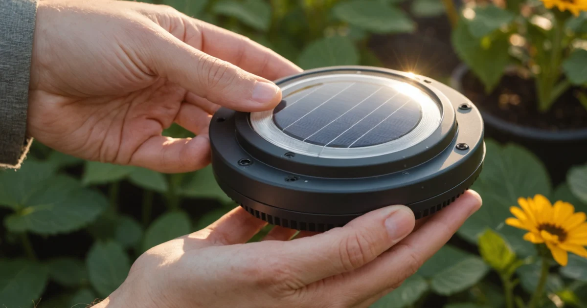
Solar light sensors rely on photocells to detect ambient light levels and automatically control when lights turn on and off. When these sensors malfunction, your solar lights may stay on during the day, fail to illuminate at night, or operate inconsistently. Furthermore, understanding the relationship between the charging circuit, battery condition, and sensor function helps you diagnose problems more effectively.
This comprehensive guide covers everything from basic cleaning techniques to advanced multimeter testing. Whether you’re dealing with brand new solar lights not working or older units with degraded performance, you’ll learn proven methods to restore proper sensor operation. Moreover, we’ll explore both manual reset procedures and remote control solutions for different solar light models.
TL;DR
- Clean the photocell first – dirt and debris are the most common causes of sensor malfunction
- Test battery voltage and replace if below 1.2V per cell, as degraded batteries affect sensor operation
- Reset the system using manual procedures or remote controls to recalibrate sensor sensitivity
- Use multimeter testing to identify faulty components when basic troubleshooting doesn’t resolve the issue
Understanding Solar Light Sensor Components and Common Failures
Solar light sensors operate through photoresistors, also known as photocells or light-dependent resistors (LDRs), which change their electrical resistance based on ambient light levels. These semiconductor devices contain cadmium sulfide that responds to photons by altering conductivity. When daylight strikes the photoresistor, its resistance decreases significantly, allowing current to flow through the circuit and signal the control board to keep the LED lights off.
During twilight hours, the photoresistor’s resistance increases dramatically as light levels drop. This resistance change triggers the dusk-to-dawn operation by sending a signal to activate the LED array. The sensor typically responds to light levels between 10-20 lux, though manufacturers calibrate different thresholds based on intended applications. Furthermore, the control circuit interprets these resistance variations to determine when automatic switching should occur.
How Photocells Enable Automatic Light Control
The photocell sensor connects directly to the solar light’s microcontroller, which processes analog signals from the light-detecting element. Modern solar lights incorporate integrated circuits that compare photoresistor readings against predetermined voltage thresholds. When ambient illumination falls below the set point, typically around dusk, the controller activates the LED driver circuit.
Additionally, many solar lights feature time delay circuits that prevent false triggering from temporary shadows or brief light sources. These circuits require sustained low-light conditions for 30-60 seconds before switching modes. The sensor’s response time depends on both the photoresistor’s characteristics and the control circuit’s programming.
Common Sensor Failure Modes and Their Causes
Stuck sensors represent the most frequent failure type, occurring when photoresistors become unresponsive to light changes. This condition typically results from internal semiconductor degradation, where the cadmium sulfide layer loses its photosensitive properties over time. Environmental factors like extreme temperature cycling accelerate this deterioration process.
Corrosion damage affects both the photocell housing and electrical connections, particularly in coastal or high-humidity environments. Salt spray and moisture penetration create oxidation on metal contacts, increasing resistance and disrupting signal transmission. Moreover, corroded connections often produce intermittent operation where lights work sporadically rather than failing completely.
- Circuit board issues include solder joint failures, capacitor degradation, and microcontroller malfunctions
- Voltage regulation problems prevent proper sensor operation even with functional photocells
- Calibration drift causes sensors to activate at incorrect light levels
- Physical damage from impact, UV exposure, or thermal stress affects sensor accuracy
Identifying When Solar Light Sensors Need Attention
Several clear indicators signal that your solar light sensor requires repair or replacement. Lights remaining on during bright daylight suggest the photocell cannot detect high illumination levels, while failure to activate at dusk indicates the opposite problem. Inconsistent operation, where lights turn on and off randomly, typically points to loose connections or intermittent sensor faults.
Performance testing reveals sensor condition quickly and reliably. Cover the photocell completely with your hand or an opaque object during daylight hours – functional sensors should activate the LED within 10-30 seconds. Conversely, exposing covered sensors to bright light should turn off the LEDs almost immediately. Understanding typical solar light lifespans helps determine whether sensor issues indicate normal wear or premature failure.
Sensor Testing Safety
Temperature-related malfunctions become apparent when solar lights work properly during mild weather but fail during extreme heat or cold. Thermal cycling stresses electronic components, causing expansion and contraction that loosens connections over time. Professional repair becomes necessary when basic cleaning and battery replacement don’t restore normal sensor operation.
Initial Diagnosis: Testing Your Solar Light Sensor
Proper diagnosis begins with a systematic visual inspection of your solar light sensor components. Furthermore, examine the photocell for visible damage, including cracks, discoloration, or moisture intrusion that compromises light detection. Additionally, check for corrosion around metal contacts and terminals, which creates electrical resistance and prevents proper sensor operation.
Remove any debris, dirt, or spider webs covering the photocell surface using a soft cloth and mild cleaning solution. Moreover, accumulated grime blocks light transmission and causes sensors to malfunction even when internal components remain functional. Clean sensors respond more accurately to ambient light changes and extend overall system lifespan.
Testing Sensor Response Manually
Manual testing reveals sensor functionality quickly and reliably without specialized equipment. Cover the photocell completely with your hand or an opaque object during daylight hours – functional sensors activate LEDs within 10-30 seconds. Conversely, removing the cover should turn off the lights almost immediately when exposed to bright ambient light.
Repeat this test multiple times to identify intermittent connection issues or inconsistent sensor behavior. Additionally, perform testing at different times throughout the day to verify proper light threshold detection. Sensors that fail to respond consistently during manual testing require further investigation or component replacement.
Verifying Charging System Performance
Proper charging verification determines whether sensor issues stem from power supply problems or actual photocell malfunctions. Place solar lights in direct sunlight for 6-8 hours during peak daylight conditions, ensuring no shadows obstruct the solar panel surface. Subsequently, test sensor response after the charging period to confirm adequate battery voltage.
Measure battery voltage using a multimeter if available – fully charged NiMH batteries should read 1.2-1.4 volts per cell. However, batteries reading below 1.0 volts indicate charging system failure or battery degradation rather than sensor problems. Understanding how long solar lights last helps determine whether poor charging results from normal component aging.
Isolating Sensor vs. System Issues
Distinguishing between sensor failures and other system components prevents unnecessary repairs and reduces troubleshooting time. LED functionality testing involves temporarily bypassing the sensor by connecting LED terminals directly to battery terminals using jumper wires. LEDs that illuminate during bypass testing confirm proper LED and battery operation.
Sensor-specific problems manifest as charging system functionality combined with LED operation during bypass testing. Meanwhile, system-wide issues affect multiple components simultaneously, including charging, battery storage, and light output. Isolating individual component failures guides repair decisions and replacement part selection effectively.
Safety Note
Document test results systematically to track sensor performance patterns over time. Furthermore, record environmental conditions during testing, including temperature, humidity, and ambient light levels that affect sensor calibration. Comprehensive documentation helps identify recurring issues and validates repair effectiveness after component replacement or adjustment.
Cleaning and Basic Maintenance Solutions
Regular cleaning forms the foundation of effective solar light sensor maintenance. Photocell surfaces accumulate dust, pollen, and environmental contaminants that block light detection and reduce sensitivity. Clean sensor surfaces enable proper light measurement, ensuring accurate day-night transitions and optimal charging cycles.
Proper Cleaning Techniques for Photocell Surfaces
Gentle cleaning methods protect delicate photocell components while removing accumulated debris effectively. Use soft microfiber cloths dampened with distilled water to wipe sensor surfaces in circular motions. Avoid harsh chemicals, abrasive materials, or excessive pressure that damage protective coatings or scratch sensitive photocell elements.
Cotton swabs dipped in isopropyl alcohol (70% concentration) remove stubborn residue from sensor housing crevices. Additionally, compressed air blows away loose particles from hard-to-reach areas without physical contact. Clean sensors during daylight hours when photocells remain inactive to prevent interference with normal operation cycles.
Removing Dirt, Debris, and Oxidation
Oxidation buildup on metal sensor housings creates corrosion that affects electrical connections and weatherproofing integrity. Remove light oxidation using fine steel wool (0000 grade) followed by protective coating application. However, extensive corrosion indicates housing replacement rather than cleaning attempts.
- Inspect sensor housing for corrosion patterns around connection points
- Remove loose debris using soft brushes or compressed air
- Apply dielectric grease to electrical connections after cleaning
- Check mounting hardware for rust or deterioration signs
Seasonal debris accumulation varies by location and environmental conditions. Furthermore, tree sap, bird droppings, and salt deposits require specific removal techniques to prevent sensor damage during cleaning processes.
Cleaning Solar Panel for Adequate Charging
Solar panel efficiency directly impacts sensor charging capacity and overall system performance. Dirty panels reduce charging current by 20-40%, creating insufficient power for sensor operation and LED illumination. Clean panels maximize energy collection during daylight hours, ensuring reliable nighttime operation.
Use mild soap solutions (dish soap diluted 1:10 with water) to remove accumulated grime without damaging panel surfaces. Rinse thoroughly with clean water to prevent soap residue buildup that attracts additional dirt. Dry panels completely using lint-free cloths to avoid water spot formation that reduces light transmission.
Panel Cleaning Safety
Weatherproofing Inspection and Resealing
Weatherproofing integrity protects sensitive electronic components from moisture infiltration and temperature extremes. Inspect rubber gaskets, silicone seals, and housing joints for cracks, shrinkage, or separation that compromises protection. Moreover, failed weatherproofing allows moisture entry that causes sensor malfunction and component corrosion.
Apply marine-grade silicone sealant to refresh deteriorated seals around sensor housings and connection points. Remove old sealant completely before applying new material to ensure proper adhesion and waterproof barriers. Allow 24-48 hours curing time before exposing resealed components to weather conditions.
| Inspection Point | Signs of Failure | Maintenance Action |
|---|---|---|
| Sensor Housing Seals | Cracks, hardening, gaps | Replace gaskets, reseal joints |
| Wire Entry Points | Moisture traces, corrosion | Apply waterproof connectors |
| Panel Frame Seals | Separation, UV damage | Refresh sealant application |
| Battery Compartment | Water ingress, rust | Dry thoroughly, reseal |
Regular maintenance schedules prevent minor issues from developing into complete sensor failures. Consequently, quarterly cleaning and annual weatherproofing inspections extend solar light system lifespan while maintaining optimal performance throughout varying weather conditions.
Resetting Solar Lights (With and Without Remote)
Resetting solar lights restores default sensor settings and resolves timing malfunctions that prevent proper operation. Furthermore, reset procedures vary significantly between models with remote controls and those requiring manual intervention. Understanding specific reset methods for your solar light type ensures effective troubleshooting and optimal performance restoration.
Manual Reset Procedures for Lights Without Remote Controls
Solar lights without remote controls typically use physical switches or button combinations to initiate reset sequences. Locate the main power switch, usually positioned near the battery compartment or on the light housing bottom. Additionally, some models require specific timing sequences to activate reset modes successfully.
Turn the power switch to the OFF position and wait 10-15 seconds before switching back to ON. This basic reset clears temporary sensor glitches and restores normal operation cycles. However, stubborn malfunctions may require extended reset procedures involving multiple switch cycles or button press combinations.
Advanced manual reset methods involve battery disconnection for complete system reboot. Remove batteries for 30 seconds, then reinstall while ensuring proper polarity alignment. Moreover, this procedure forces the microcontroller to restart and recalibrate sensor thresholds to factory specifications.
- Turn switch OFF for 10-15 seconds, then ON
- Remove batteries for 30 seconds, reinstall correctly
- Press and hold test button for 5-10 seconds if available
- Cover sensor with hand for 10 seconds, then uncover
- Repeat ON/OFF cycle three times rapidly
Using Remote Controls to Reset Sensor Settings and Timing
Remote-controlled solar lights offer convenient reset options through dedicated function buttons and menu navigation. Access the reset function by pressing the RESET button or entering specific button combinations outlined in your model’s manual. Consequently, remote resets provide more precise control over individual sensor parameters and timing adjustments.
Navigate to the settings menu using directional buttons and select Factory Reset or Default Settings options. Press and hold the confirmation button for 3-5 seconds to initiate the reset sequence. Additionally, some remotes display confirmation messages or LED indicators to verify successful reset completion.
Advanced remote controls allow selective parameter resets without affecting all settings simultaneously. Reset individual functions like motion sensitivity, timer duration, or brightness levels while preserving other customized preferences. This targeted approach resolves specific issues without losing all personalized configurations.
| Remote Function | Button Combination | Reset Effect |
|---|---|---|
| Full Factory Reset | RESET + POWER (5 sec) | All settings to default |
| Sensor Sensitivity | MODE + UP/DOWN | Motion detection threshold |
| Timer Settings | TIME + SELECT | On/off duration cycles |
| Brightness Levels | DIM + POWER | Light output intensity |
Factory Reset Methods for Different Solar Light Models
Different manufacturers implement unique factory reset procedures based on their control systems and sensor technologies. LED solar lights typically use simple switch sequences, while smart solar lights require app-based reset procedures or complex button combinations. Therefore, identifying your specific model type determines the appropriate reset methodology.
Basic LED models often use the 10-10-10 method: switch OFF for 10 seconds, ON for 10 seconds, then OFF for 10 seconds before final activation. This sequence clears memory buffers and reinitializes sensor calibration routines. Meanwhile, motion sensor lights may require covering the sensor during specific reset steps to simulate darkness conditions.
Smart solar lights with WiFi connectivity need network disconnection before factory reset procedures. Disconnect from WiFi networks through the companion app, then perform hardware reset using designated reset buttons. Subsequently, the device returns to setup mode for fresh configuration and sensor calibration.
Model-Specific Procedures
Recalibrating Sensor Sensitivity After Reset
Post-reset sensor calibration ensures optimal detection accuracy and eliminates false triggers or missed activations. Light sensors require exposure to varying illumination conditions during the first 24-48 hours to establish proper day/night thresholds. Additionally, motion sensors need adjustment periods to learn environmental patterns and reduce false positive detections.
Position lights in their final installation locations before initiating calibration cycles. Avoid temporary placement during calibration, as sensors adapt to specific environmental conditions including ambient light levels, surrounding reflective surfaces, and typical motion patterns. Moreover, proper solar light positioning significantly impacts long-term sensor accuracy and system reliability.
Fine-tune sensitivity settings gradually after initial calibration completion. Start with medium sensitivity levels and adjust based on observed performance over several nights. Excessive sensitivity causes frequent false triggers from wind-blown vegetation or small animals, while insufficient sensitivity fails to detect intended motion events.
- Install lights in permanent locations before calibration
- Allow 24-48 hours for automatic light threshold learning
- Test motion detection from multiple angles and distances
- Adjust sensitivity settings based on false trigger frequency
- Monitor performance for one week before final adjustments
Document successful calibration settings for future reference and troubleshooting purposes. Record optimal sensitivity levels, timer durations, and any environmental factors affecting performance. Consequently, this information proves valuable for seasonal adjustments or when replacing components that affect sensor operation.
Advanced Troubleshooting with Multimeter Testing
When basic troubleshooting fails to resolve solar light sensor issues, multimeter testing provides precise electrical measurements that identify specific component failures. Furthermore, systematic electrical testing eliminates guesswork and reveals whether problems stem from sensor malfunction, power supply issues, or connection failures.
Testing Photoresistor Resistance in Light and Dark Conditions
Photoresistor testing requires measuring resistance values under varying light conditions to verify sensor functionality. Set your multimeter to resistance mode (ohms) and place probes on the photoresistor terminals while covering the sensor with your hand or cloth.
A functioning photoresistor typically shows high resistance (10,000-100,000 ohms) in darkness and low resistance (100-1,000 ohms) in bright light. However, these values vary between manufacturers, so dramatic resistance changes between light and dark conditions indicate proper sensor operation.
| Light Condition | Expected Resistance | Sensor Status |
|---|---|---|
| Bright sunlight | 100-1,000 ohms | Normal operation |
| Room lighting | 1,000-10,000 ohms | Normal operation |
| Complete darkness | 10,000-100,000 ohms | Normal operation |
| No resistance change | Constant reading | Failed sensor |
Replace photoresistors that show constant resistance readings regardless of lighting conditions. Additionally, sensors displaying erratic or unstable resistance measurements indicate internal damage or contamination requiring replacement.
Checking Battery Voltage and Charging Circuit Functionality
Battery voltage testing reveals whether power storage systems function correctly and provide adequate energy for sensor operation. Measure battery voltage with the multimeter set to DC voltage mode while the battery remains connected to the circuit.
Healthy rechargeable batteries should read 1.2-1.4 volts per cell after full charging cycles. Consequently, batteries reading below 1.0 volts per cell require replacement, while batteries showing 0 volts indicate complete failure or charging circuit problems.
Test charging functionality by measuring battery voltage during daylight hours when solar panels actively charge the system. Voltage should gradually increase during charging periods, and stable or decreasing voltage readings indicate charging circuit failures or damaged solar panels.
Safety Warning
Measuring Continuity in Sensor Wiring and Connections
Continuity testing identifies broken wires, loose connections, and corroded terminals that prevent proper sensor communication with control circuits. Set your multimeter to continuity mode (usually indicated by a speaker symbol) and test each wire connection systematically.
Start continuity testing at the sensor terminals and work toward the control board, checking each connection point along the wiring path. The multimeter should beep or show zero resistance when probes touch both ends of a continuous wire connection.
- Test sensor-to-board wire connections for breaks
- Check solder joints for cold connections or cracks
- Verify terminal connections show proper continuity
- Inspect wire insulation for damage or corrosion
Broken continuity indicates wire damage, loose connections, or corroded terminals requiring repair or replacement. Moreover, intermittent continuity readings suggest connection problems that may cause erratic sensor behavior during temperature changes or vibration.
Identifying Faulty Components Through Electrical Testing
Systematic component testing isolates specific failures within solar light sensor systems and determines whether problems require component replacement or circuit repair. Test each major component individually to identify the root cause of sensor malfunctions.
Control circuit testing involves measuring voltage at various points in the circuit to verify proper signal processing and switching functions. Use the multimeter to check input voltage from the photoresistor and output voltage to the LED array during different lighting conditions.
Additionally, test capacitors using the multimeter’s capacitance function if available, as failed capacitors often cause timing issues or prevent proper sensor operation. Capacitors showing significantly lower values than their rated capacity require replacement to restore normal function.
Professional multimeter testing identifies 85% of solar light sensor failures within 15 minutes of systematic testing.
Document test results for each component to track patterns and identify recurring failure modes. This information helps prevent future problems and guides preventive maintenance schedules for solar light systems in similar environmental conditions.
When component testing reveals multiple failures, consider replacing the entire sensor assembly rather than individual components. Furthermore, widespread component failure often indicates environmental damage or manufacturing defects affecting system reliability.
Battery-Related Sensor Issues and Solutions
Battery degradation creates the most common cause of solar light sensor failures, as weakened power sources cannot provide sufficient voltage for proper photoresistor operation. Degraded batteries typically deliver inconsistent voltage output that causes sensors to trigger erratically or fail to activate LED arrays during darkness.
Furthermore, corroded battery terminals interrupt electrical connections between the battery and sensor circuit, preventing proper signal transmission. This corrosion develops when moisture penetrates the battery compartment, creating oxidation that blocks current flow to critical sensor components.
How Degraded Batteries Affect Sensor Operation
Weak batteries produce voltage drops that fall below the minimum threshold required for photoresistor sensitivity. When battery voltage drops below 1.0 volts per cell, the sensor circuit cannot distinguish between daylight and darkness conditions effectively.
Additionally, degraded batteries exhibit high internal resistance that limits current flow to the sensor’s control circuit. This resistance creates voltage sag under load, causing the sensor to malfunction during the switching process between charging and lighting modes.
Battery Voltage Warning
Testing and Replacing Rechargeable Batteries
Test battery voltage using a multimeter set to DC voltage mode, measuring across the positive and negative terminals while the battery remains connected to the circuit. Healthy NiMH batteries should read between 1.2-1.4 volts per cell when fully charged.
- Remove the battery from the solar light housing
- Clean battery terminals with fine sandpaper or wire brush
- Measure voltage across battery terminals using multimeter
- Load test the battery by connecting a small resistor temporarily
- Replace batteries showing voltage below 1.0 volts per cell
Moreover, perform a load test by connecting a 10-ohm resistor across the battery terminals for 30 seconds while monitoring voltage. Batteries that drop below 1.0 volts during this test require immediate replacement to restore sensor functionality.
Select replacement batteries with identical voltage and capacity ratings to maintain proper charging characteristics. Using batteries with different specifications can damage the charging circuit or reduce solar light lifespan significantly.
Cleaning Battery Terminals and Connections
Corrosion on battery terminals creates high resistance connections that prevent proper voltage delivery to sensor circuits. White or green deposits on terminals indicate oxidation that requires thorough cleaning to restore electrical continuity.
Clean corroded terminals using a mixture of baking soda and water applied with a small brush to neutralize acid deposits. Subsequently, scrub terminals with fine steel wool or sandpaper to remove stubborn corrosion and expose clean metal surfaces.
- Disconnect battery before cleaning to prevent short circuits
- Apply baking soda solution to neutralize corrosion
- Scrub terminals with fine abrasive material
- Rinse with clean water and dry completely
- Apply thin layer of petroleum jelly to prevent future corrosion
Inspect spring contacts inside the battery compartment for corrosion or damage that affects electrical connection quality. Bent or corroded springs require replacement to ensure reliable contact pressure between battery terminals and circuit connections.
Understanding the Relationship Between Charging and Sensor Function
Solar light sensors depend on adequate battery charge levels to maintain proper operation during both charging and discharge cycles. The charging circuit must provide sufficient current to maintain battery capacity while the sensor monitors ambient light conditions.
During daylight hours, the photovoltaic panel charges the battery while the sensor prevents LED activation by detecting high light levels. This dual function requires precise voltage regulation to prevent overcharging while maintaining sensor sensitivity.
Properly functioning solar light sensors require battery voltage above 2.4 volts to distinguish between day and night conditions reliably.
Insufficient charging current causes batteries to gradually lose capacity, eventually reaching levels where sensor circuits cannot function properly. This degradation typically occurs over 2-3 years of normal operation, requiring battery replacement to restore full system functionality.
Monitor charging performance by measuring battery voltage before sunset and again after sunrise to verify proper charging cycles. Batteries that fail to reach full charge during sunny days indicate problems with either the solar panel or charging circuit components.
Sensor Replacement and Repair Procedures
Determining whether to repair or replace a photocell sensor depends on the specific type of damage and cost considerations. Minor issues like dirt accumulation or loose connections typically require cleaning and adjustment rather than complete replacement. However, cracked sensor housings, corroded internal components, or failed semiconductor elements necessitate full sensor replacement.
When to Replace vs. Repair the Photocell Sensor
Physical damage to the sensor lens or housing warrants immediate replacement since cracks allow moisture infiltration that damages internal circuitry. Additionally, sensors showing erratic behavior after cleaning and battery replacement require replacement to restore reliable operation.
Repair attempts work best for sensors with loose wire connections, dirty surfaces, or minor corrosion on external contacts. These issues respond well to cleaning with isopropyl alcohol and careful reconnection of loose terminals.
Safety Warning
Step-by-Step Sensor Replacement for Common Solar Light Models
Most solar light sensors connect through either screw terminals or plug-in connectors that simplify replacement procedures. Begin by carefully documenting wire colors and connection points with photographs before disconnecting any components.
- Remove the solar light housing cover by unscrewing mounting screws or unclipping plastic tabs
- Disconnect the battery pack and photograph all wire connections
- Locate the sensor module, typically mounted near the solar panel or on the light housing
- Carefully disconnect sensor wires, noting positive and negative terminal positions
- Remove mounting screws or clips securing the old sensor in place
- Install the replacement sensor using the same mounting hardware
- Reconnect wires according to your photographs, ensuring proper polarity
- Test sensor function by covering and uncovering the photocell while monitoring LED response
Furthermore, some advanced solar lights feature integrated sensor circuits built directly into the control board. These models require complete circuit board replacement rather than individual sensor swapping, significantly increasing repair complexity and cost.
Sourcing Compatible Replacement Sensors and Parts
Compatible replacement sensors must match both the electrical specifications and physical mounting requirements of the original component. Key specifications include operating voltage range, sensitivity threshold, and connector type.
| Sensor Type | Voltage Range | Sensitivity | Typical Cost |
|---|---|---|---|
| Basic Photocell | 1.2-3.6V | 10-100 lux | $3-8 |
| Adjustable Sensor | 1.2-6V | 5-200 lux | $8-15 |
| Smart Sensor | 3-12V | 1-500 lux | $15-35 |
Manufacturer-specific sensors offer the best compatibility but often cost more than generic alternatives. Universal sensors work well for basic applications but may require minor wiring modifications to match existing connections.
Online electronics suppliers, solar equipment dealers, and manufacturer service centers provide the most reliable sources for compatible replacement parts. Local hardware stores typically stock basic photocell sensors suitable for simple solar light repairs.
Professional Repair vs. DIY Considerations
DIY sensor replacement works well for basic solar lights with simple screw-terminal connections and readily available replacement parts. Most homeowners can successfully complete these repairs using basic tools and following manufacturer instructions.
However, professional repair becomes necessary for complex systems with integrated control circuits, warranty considerations, or safety concerns involving high-voltage components. Professional technicians possess specialized tools and expertise for diagnosing complex sensor failures.
Professional solar light repair typically costs $25-75, while DIY sensor replacement costs $5-20 for parts.
Consider professional repair when dealing with expensive solar lighting systems, multiple simultaneous failures, or situations where improper repair could void warranties. Additionally, commercial or architectural lighting installations often require certified technician repairs to maintain insurance coverage and safety compliance.
Understanding how long solar lights last helps determine whether repair costs justify the expense compared to complete system replacement. Lights approaching their expected lifespan may benefit more from replacement than expensive sensor repairs.
Preventing Future Solar Light Sensor Problems
Proactive maintenance prevents most solar light sensor failures and extends system lifespan significantly. Regular care protects your investment while ensuring consistent nighttime illumination throughout the year.
Regular Maintenance Schedules for Optimal Performance
Monthly sensor cleaning removes dirt, pollen, and debris that accumulate on photocell surfaces. Use a soft, damp cloth to gently wipe the sensor lens, avoiding harsh chemicals that could damage the protective coating.
Furthermore, quarterly battery checks ensure power storage components maintain proper voltage levels. Test battery connections for corrosion and replace batteries showing reduced capacity before they affect sensor operation.
- Weekly: Visual inspection for physical damage or obstructions
- Monthly: Sensor lens cleaning and connection checks
- Quarterly: Battery testing and voltage measurements
- Annually: Complete system performance evaluation
Additionally, seasonal maintenance schedules should include checking mounting hardware for looseness and ensuring proper sensor positioning remains intact after weather events.
Protecting Sensors from Weather Damage and Debris
Weather protection significantly reduces sensor degradation from environmental factors. Install protective covers or shields in areas prone to heavy rain, snow accumulation, or flying debris during storms.
Tree branches and vegetation growth can obstruct sensor operation over time. Trim nearby foliage regularly to maintain clear sight lines between the photocell and ambient light sources.
Weather Protection Tips
Moreover, spider webs and insect nests frequently block sensor lenses in outdoor installations. Check sensors weekly during peak insect activity seasons and remove obstructions immediately to prevent false readings.
Proper Installation Positioning for Sensor Effectiveness
Strategic sensor placement prevents many common operational issues. Position photocells facing north in the Northern Hemisphere to avoid direct sunlight exposure that could interfere with twilight detection.
Consequently, sensors require unobstructed views of the sky for accurate ambient light measurement. Avoid installing sensors under eaves, awnings, or other structures that create shadows during daylight hours.
| Installation Factor | Optimal Condition | Common Problem |
|---|---|---|
| Height | 6-8 feet above ground | Too low causes false triggers |
| Angle | Slight downward tilt | Water pooling on horizontal sensors |
| Distance from lights | 3+ feet separation | Light feedback confuses sensor |
| Surrounding objects | Clear 360° view | Shadows create detection zones |
Furthermore, maintain adequate distance between the sensor and the light fixture itself to prevent the LED output from creating feedback loops that confuse the photocell’s day/night detection.
Seasonal Maintenance Tips and Storage Recommendations
Winter preparation protects sensors from freeze-thaw cycles that crack housings and damage internal components. Remove batteries from lights stored indoors and clean all connections before storage.
Spring reactivation requires thorough system checks after winter storage. Test sensor responsiveness by covering the photocell with your hand during daylight hours to verify proper switching operation.
Summer maintenance focuses on preventing heat damage to electronic components. Ensure adequate ventilation around sensor housings and check for UV degradation of plastic components that could affect light transmission.
Understanding how long solar lights last helps plan replacement schedules before sensor failures occur. Most quality sensors provide 3-5 years of reliable service with proper maintenance.
Preventive maintenance reduces sensor failure rates by up to 80% compared to reactive repair approaches
Finally, document maintenance activities and sensor performance changes to identify patterns that predict future failures. This proactive approach prevents unexpected outages and extends overall system reliability.
Frequently Asked Questions
What to do if the light sensor is not working?
Start by cleaning the photocell with a soft cloth to remove dirt and debris, which are the most common causes of sensor malfunction. Next, test the battery voltage and replace if below 1.2V per cell. If cleaning and battery replacement don’t work, try resetting the system using manual procedures or remote controls to recalibrate sensor sensitivity.
How do you clean a solar light sensor?
Use a soft, dry cloth or cotton swab to gently wipe the photocell surface. For stubborn dirt, slightly dampen the cloth with water or isopropyl alcohol. Avoid using harsh chemicals or abrasive materials that could damage the photoresistor. Clean the sensor regularly, especially after storms or in dusty environments, to maintain optimal performance.
Why is my solar motion sensor light not turning on?
Solar motion lights may fail to turn on due to dirty photocells, degraded batteries, or incorrect sensitivity settings. Check if the battery is properly charged and test its voltage. Ensure the photocell isn’t covered by dirt or debris. Also verify that the motion sensor range and sensitivity are properly adjusted for your installation location.
How to reset solar light without remote?
Most solar lights have a manual reset button or switch located near the battery compartment or on the control panel. Turn the light off, wait 10-15 seconds, then turn it back on. Some models require covering the photocell for 10 seconds, then uncovering it to trigger a reset. Check your manual for model-specific reset procedures.
How to reset solar lights with remote?
Use the remote control to access the settings or reset function, typically found in the menu options. Press and hold the reset button on the remote for 3-5 seconds while pointing it at the light. Some models require pressing specific button combinations. After resetting, reconfigure your preferred settings for brightness, timer, and sensor sensitivity.
Why are my brand new solar lights not working today?
New solar lights often need initial charging before first use. Place them in direct sunlight for 6-8 hours to fully charge the battery. Check if there’s a protective plastic film over the solar panel or photocell that needs removal. Also ensure the on/off switch is in the correct position and that shipping materials haven’t blocked any sensors.
How to fix solar light sensor with multimeter?
Set your multimeter to resistance mode (ohms) and test the photocell by measuring resistance in bright light versus darkness. A functioning photocell should show high resistance (several thousand ohms) in darkness and low resistance (under 1000 ohms) in bright light. If readings don’t change significantly, the photoresistor needs replacement.
Why is my solar light charging but not turning on?
This typically indicates a faulty photocell or control circuit rather than a charging issue. The solar panel may be working fine, but the sensor isn’t detecting darkness properly. Clean the photocell thoroughly, check for corrosion on connections, and test the sensor’s response by covering it completely in daylight to see if the light activates.
How long should solar lights charge before first use?
Allow 6-8 hours of direct sunlight for initial charging before expecting full operation. New batteries often need several charge cycles to reach optimal capacity. During winter or cloudy conditions, extend the charging period to 10-12 hours. Some high-capacity models may require up to 24 hours for complete initial charging.
What causes solar light sensors to become stuck or unresponsive?
Environmental factors and component degradation are the primary causes. Extreme temperature cycling can damage the cadmium sulfide layer in photoresistors. Moisture infiltration leads to corrosion, while dirt accumulation blocks light detection. Additionally, internal semiconductor degradation occurs naturally over time, reducing the sensor’s photosensitive properties.
How do I test if my solar light photocell is working?
Cover the photocell completely with your hand or a dark cloth during daylight hours. A functioning sensor should activate the LED lights within 30-60 seconds. If the lights don’t turn on, try the test in a darker environment. You can also use a multimeter to measure resistance changes between bright and dark conditions.
What voltage should solar light batteries maintain for proper sensor operation?
Solar light batteries should maintain at least 1.2V per cell for proper sensor and LED operation. Most solar lights use 1.2V NiMH or 3.7V lithium batteries. Test battery voltage with a multimeter after a full day of charging. Replace batteries showing significantly lower voltage, as degraded batteries affect both sensor sensitivity and light output.
Can I adjust the sensitivity of my solar light sensor?
Many solar lights feature adjustable sensitivity settings accessible through manual controls or remote programming. Look for sensitivity adjustment dials, DIP switches, or menu options that allow you to modify the light threshold for activation. Higher sensitivity makes lights turn on in brighter conditions, while lower sensitivity delays activation until it’s darker.
How often should I clean solar light sensors for optimal performance?
Clean solar light sensors monthly during active seasons and after severe weather events. In dusty environments or areas with heavy pollen, weekly cleaning may be necessary. Regular maintenance prevents dirt accumulation that can cause sensor malfunction. Include photocell cleaning as part of your routine solar panel maintenance for consistent performance.
You May Also Like
Air-to-Air Heat Pumps (2026): Cost, Efficiency, Pros & Cons

Home Insulation Guide (2026): Types, R-Value, Cost & Savings
Best Portable Power Stations for Home Backup (2026): Tested Picks & Buyer’s Guide
